
Liquid discharge head and circuit board

a liquid discharge head and circuit board technology, applied in printed circuits, printing, electrical apparatus, etc., can solve problems such as noise, inability to normally perform inability to influence transmission of logical signals, so as to reduce the influence of noise when data transfer is performed using the lvds transmission schem

Active Publication Date: 2014-03-18
CANON KK
View PDF4 Cites 3 Cited by
  • Summary
  • Abstract
  • Description
  • Claims
  • Application Information

AI Technical Summary

Benefits of technology

The present invention is about reducing the impact of noise when using the LVDS transmission scheme to transfer data on a circuit board. It does this by including a pair of differential transmission lines on one side of the board and a voltage supply line on the other side. This design helps to improve the reliability of the liquid discharge head or circuit board while maintaining its flexibility. Ultimately, this improves the overall performance of the liquid discharge head or circuit board.

Problems solved by technology

For this reason, even in the LVDS transmission scheme which is less susceptible to noises by taking differences of the signals between a pair of differential transmission lines, there is a possibility that a switching noise when voltage is applied to the energy generating elements may exert an influence upon transmission of the logical signals.
For this reason, in a liquid discharge head discussed in Japanese Patent Application Laid-Open No. 2005-199665, there are concerns that transmission of the logical signals may not be normally performed under the influence of the switching noise, and operation may become unstable.
For this reason, it is conceivable that an electric current flowing through the flexible board also becomes large, and influence of the switching noise becomes noticeable.
To reduce the influence of noises by keeping the differential transmission line used in the LVDS transmission scheme away from the line utilized for applying voltage for generation of energy, leads to an upsizing of the flexible board, and eventually to an upsizing of the apparatus, and therefore, that is not quite realistic.

Method used


Image

  • Liquid discharge head and circuit board
  • Liquid discharge head and circuit board
  • Liquid discharge head and circuit board

Examples


Embodiment Construction

[0020]Various exemplary embodiments, features, and aspects of the invention will be described in detail below with reference to the drawings.

[0021]“Record” used in the present specification means not only imparting an image having a meaning such as characters or graphics on a recording medium, but also imparting an image having no meaning such as patterns.

[0022]Furthermore, “ink” should be broadly interpreted, and refers to a liquid served in the formation of an image, a texture, a pattern or the like, which is imparted on a recording medium, processing of the recording medium, or treatment of the ink or the recording medium. In this case, treatment of the ink or recording medium, refers to, for example, improvement of fixing property, improvement of recording quality or coloring property, and improvement in image durability, due to coagulation or insolubilization of color materials contained in the ink to be imparted on the recording medium.

[0023]FIG. 1A is a perspective view illus...


PUM


Abstract

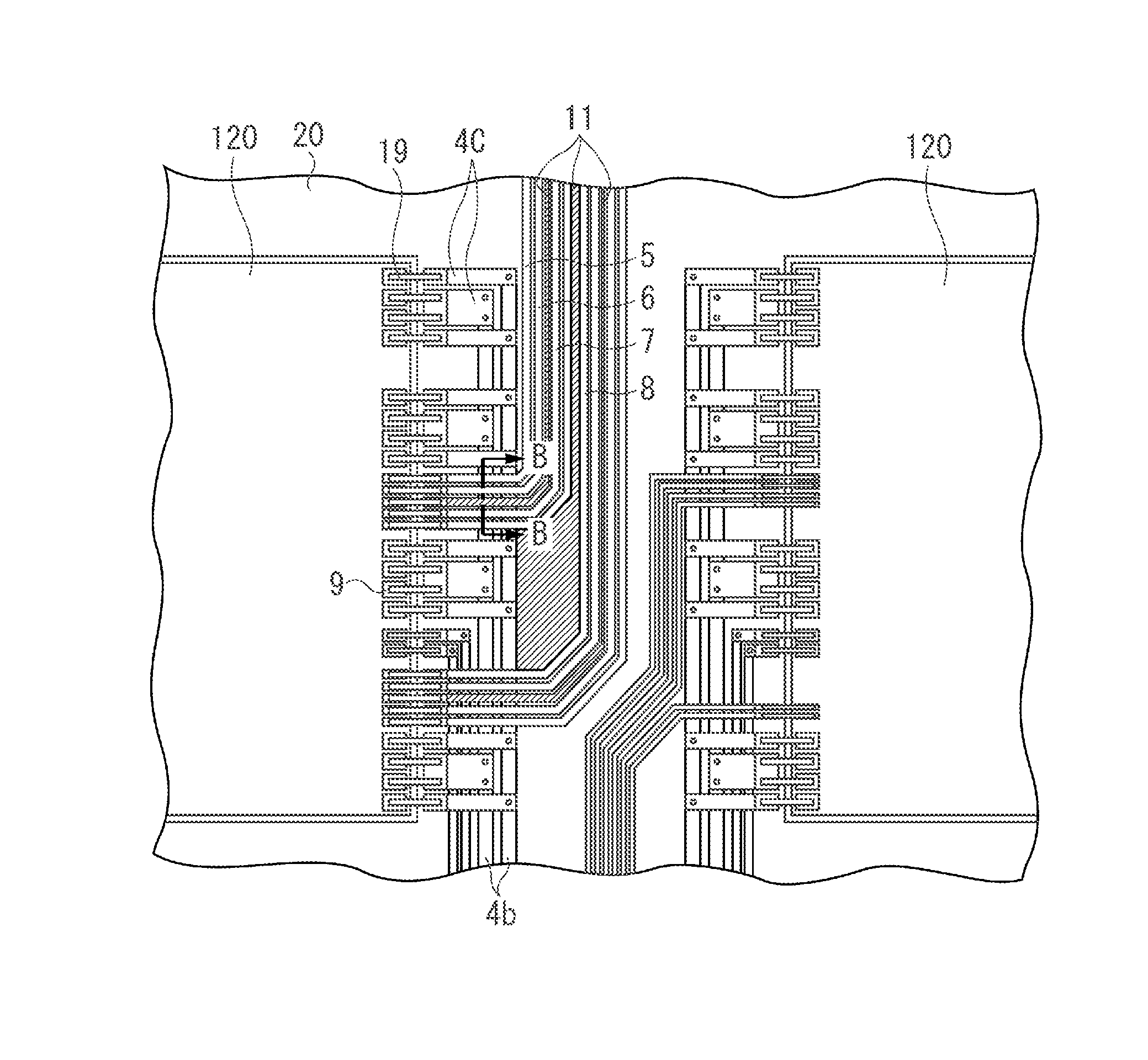
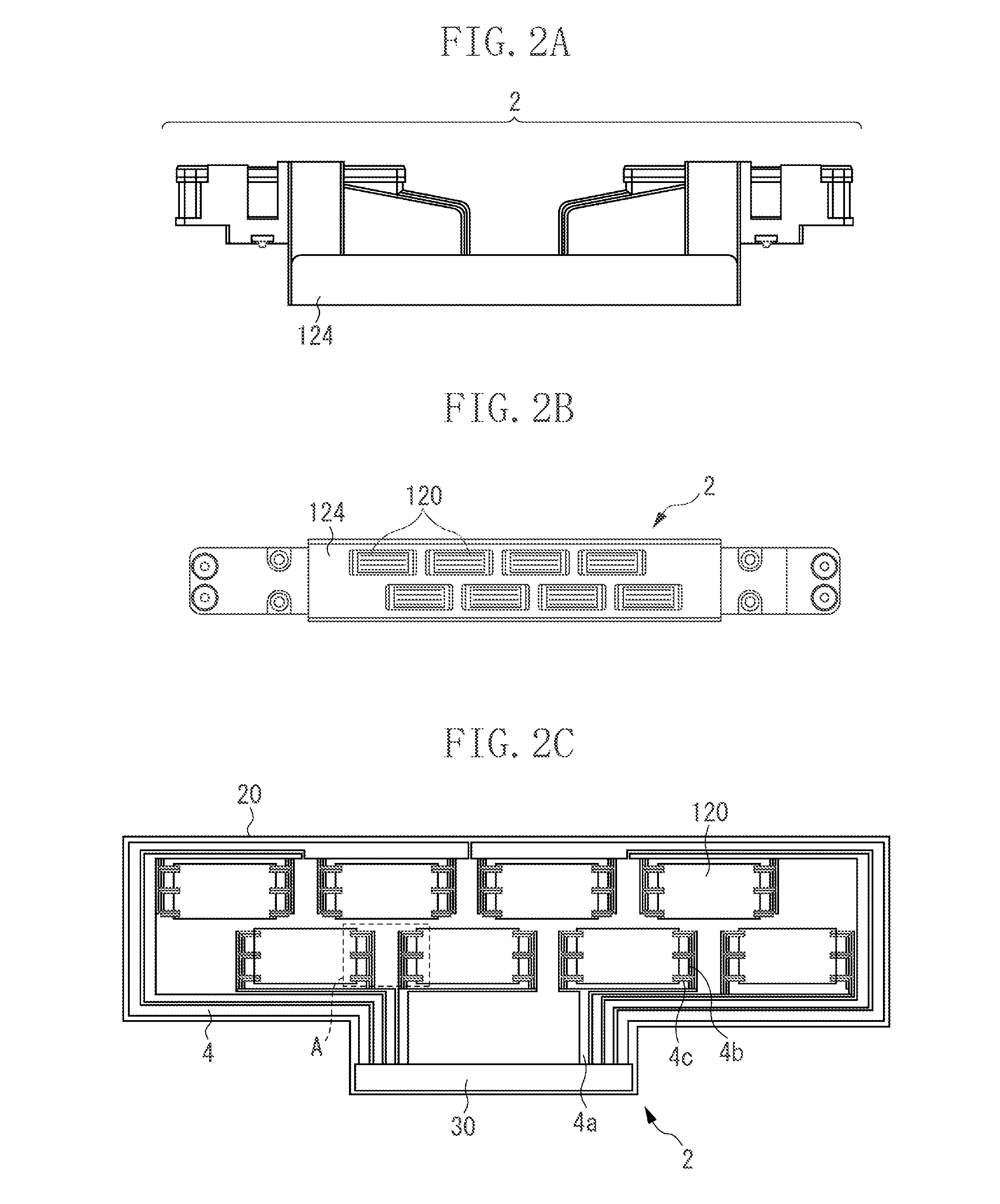
A liquid discharge head includes a liquid discharge head substrate including a discharge port through which a liquid is discharged, and a plurality of energy generating elements that generate energy for discharging the liquid from the discharge port, and a circuit board having flexibility including a pair of differential transmission lines for transmitting differential transmission signals used as logical signals for driving the energy generating elements, to the liquid discharge head substrate, and a voltage supply line for supplying a voltage applied to the energy generating elements to obtain the energy, to the liquid discharge head substrate, wherein the pair of differential transmission lines is provided on one surface of the circuit board, and the voltage supply line is provided on the other surface of the circuit board, which is on a reverse side of the one surface.

Description

BACKGROUND OF THE INVENTION[0001]1. Field of the Invention[0002]The present invention relates to a liquid discharge head and a circuit board.[0003]2. Description of the Related Art[0004]A low voltage differential signal (LVDS) transmission scheme is one of differential transmission schemes as a data transfer scheme used in the field of precision equipment such as a liquid discharge apparatus. The LVDS transmission scheme is a scheme for transferring data using a pair of differential transmission lines, and is capable of transferring the data with much lower electric potential difference at a higher speed compared with a commonly used scheme for transferring data with a single line (hereinafter, referred to as a single-ended transmission scheme).[0005]Japanese Patent Application Laid-Open No. 2005-199665 discusses a configuration for sending at high speeds using the LVDS transmission scheme, logical signals such as recorded data signals or clock signals for driving energy generating ...

Claims


Application Information

Patent Timeline
Patent Type & Authority Patents(United States)
IPC IPC(8): B41J29/38B41J2/14
CPCB41J2/14072H05K1/0228H05K1/0245
Inventor HAYASAKI, KIMIYUKITOKUDA, TAKAMITSUUMEDA, KENGOHIRAYAMA, NOBUYUKIYAMAGUCHI, TAKAAKIIMANAKA, YOSHIYUKIFURUKAWA, TATSUO
Owner CANON KK
Learn More