
Method of hydraulically fracturing a formation

a technology of hydraulic fracturing and formation, applied in the direction of fluid removal, earth-moving drilling, borehole/well accessories, etc., can solve the problems of fractures remaining propped open, fractures extending further into the formation, and formation fracturing, so as to reduce the likelihood that additional fracturing operations may be impeded by the sand in the well bor

Active Publication Date: 2014-03-11
BAKER HUGHES INC
View PDF7 Cites 5 Cited by
  • Summary
  • Abstract
  • Description
  • Claims
  • Application Information

AI Technical Summary

Benefits of technology

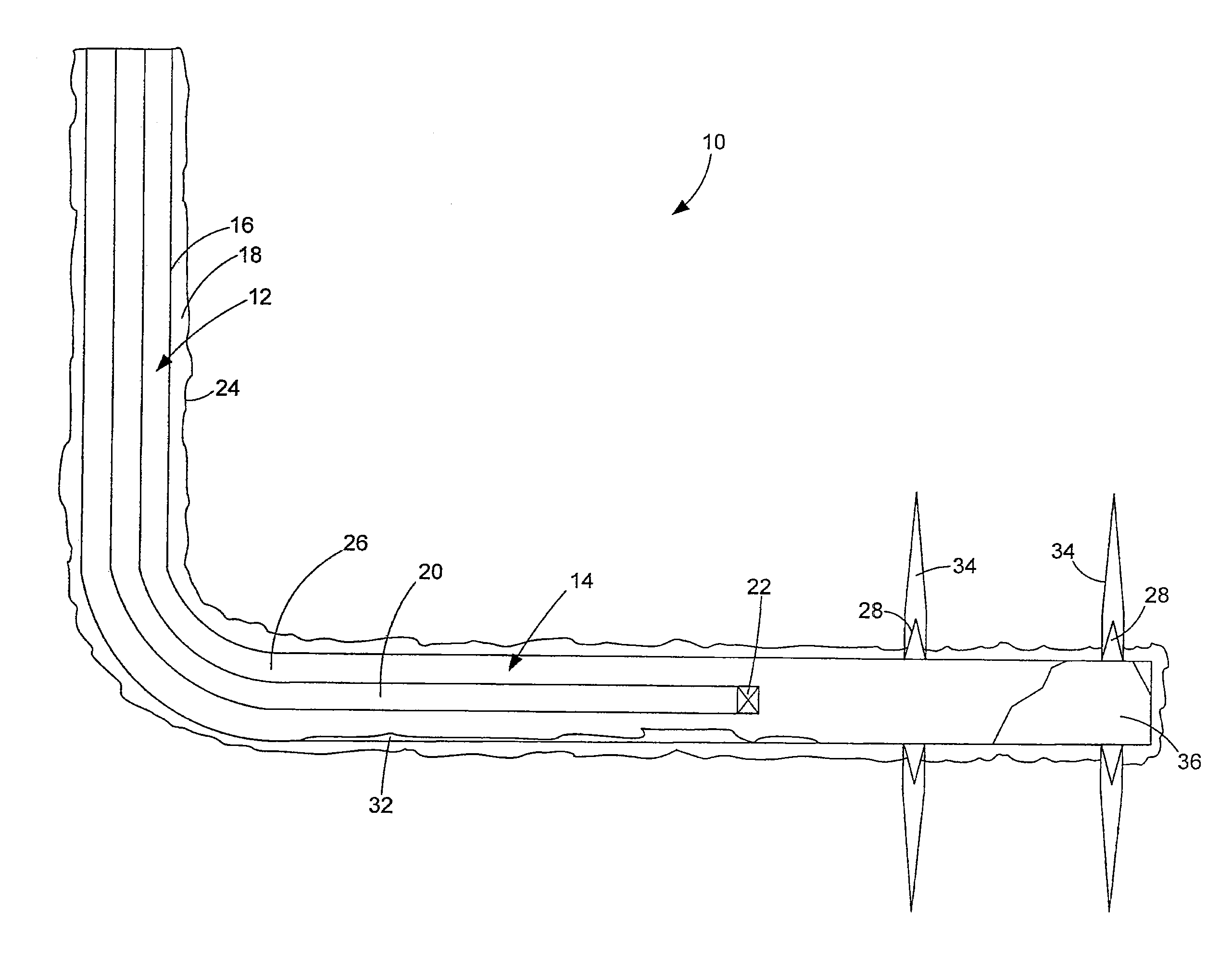
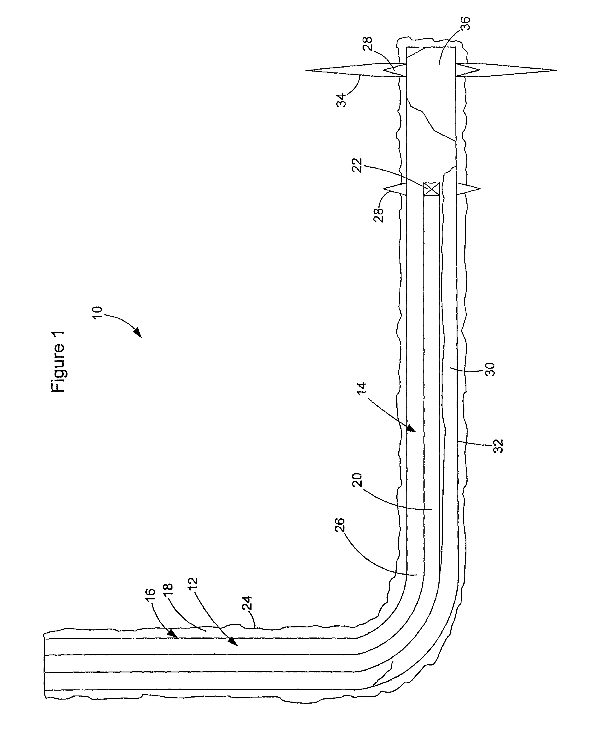
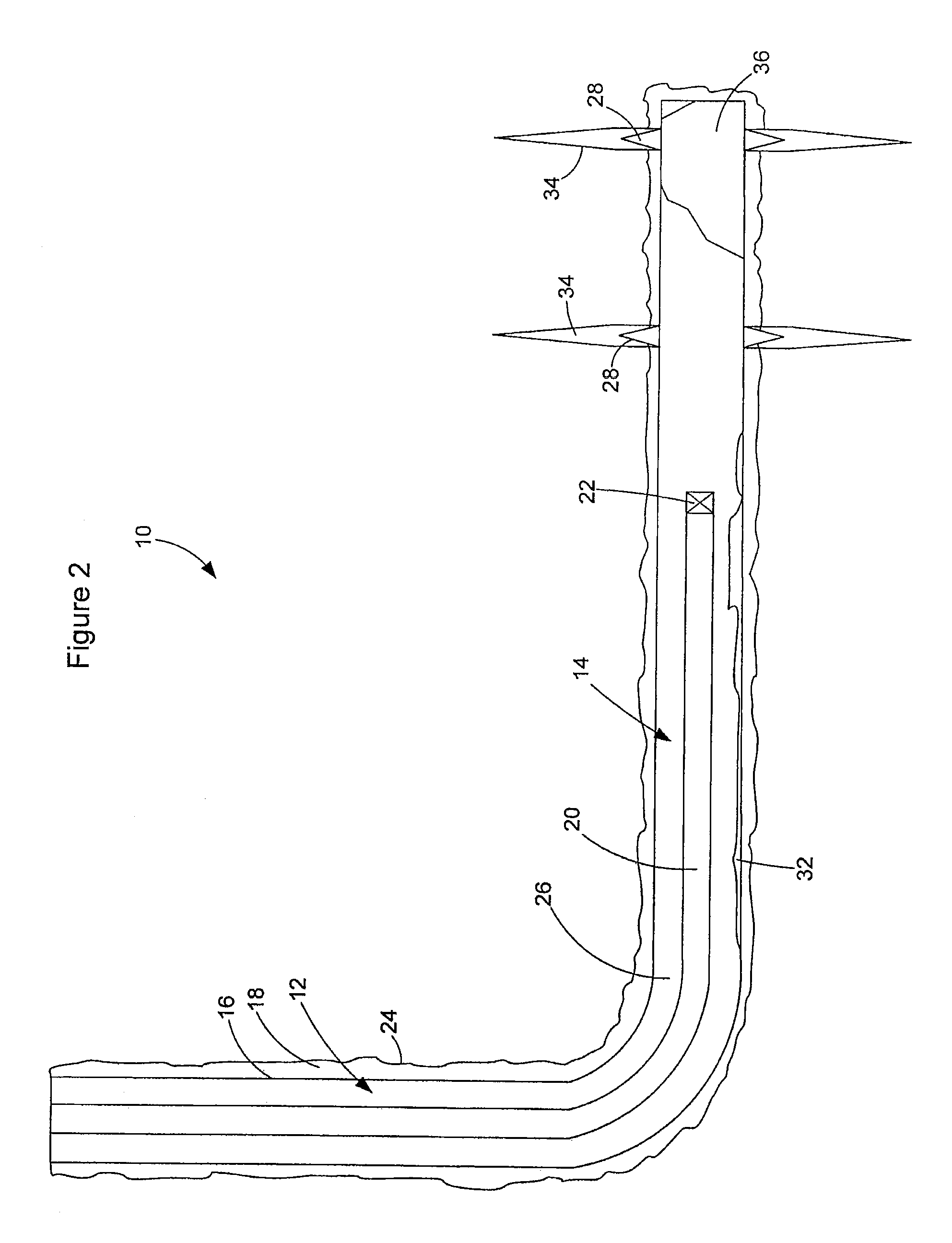
[0006]In accordance to the invention, a method is provided for treating a formation wherein the residual sand in the horizontal well bore does not prevent the fracturing of the formation. In accordance to this process, a flow regime is utilized such that the hydraulic fracturing may proceed without being impeded by re-entrainment of sand. Further, the process may be conducted so as to re-entrain sand in the horizontal well bore and utilize that sand as part of a fracturing operation. An advantage of this process is that a horizontal well bore may be reliably fractured with numerous treatments from the toe of the well to the heel, without an intermediate zone being sanded off which can result in termination of the stimulation treatment. Further, the method can result in re-entrainment of sand which is present in the horizontal section of the well thereby reducing the likelihood that additional fracturing operations may be impeded by the sand in the well bore.
[0010](i) during a first period to break down the formation while reducing pick up of sand positioned in the well bore;
[0022]In another embodiment, the method further comprises monitoring the well head pressure and reducing the flow rate of a hydraulic fracturing fluid during the first and second periods when a pressure increase indicates that sand off of the formation has occurred.
[0031]In one embodiment, the method further comprises monitoring the well head pressure and reducing the flow rate of a hydraulic fracturing fluid during the first period when a pressure increase indicates that sanding off of the formation has occurred.

Problems solved by technology

The high pressure results in the formation fracturing.
Continued pumping at high pressure and rates results in the fractures extending further into the formation.
This results in the fracture remaining propped open after the pressure is withdrawn.
However, in some cases it may take up to hours.
Due to limitations of flow rate down the coil and velocities in the annulus and the volumes pumped down the coil, sometimes the sand may tend to be deposited in the horizontal section of the well bore or at the bend between the horizontal and vertical sections of the well.
This residual sand may impede the treatment of the next zone of the horizontal section of the well bore.
Further, the method can result in re-entrainment of sand which is present in the horizontal section of the well thereby reducing the likelihood that additional fracturing operations may be impeded by the sand in the well bore.

Method used


Image

  • Method of hydraulically fracturing a formation
  • Method of hydraulically fracturing a formation
  • Method of hydraulically fracturing a formation

Examples


example 1

[0060]A standard hydraulic fracturing treatment operation is exemplified by FIG. 4. This operation was conducted subsequent to the abrasive perforation of the casing and cement. The initial process is to break down the formation. As exemplified in FIG. 4, the combined rate of fluid that is pumped into a well bore increases to 0.4 cubic meters per minute at five minutes of elapsed time. This increases the well head pressure to about 48 MPa. The pump rate is held constant until the thirty minute elapsed time mark at which time it is increased to 0.5 cubic meters per minute. The pressure gradually increases during this time until, at about fifty minutes, the pressure starts to reduce. This is considered to be the time at which the break down of the formation occurs.

[0061]The pump rate is kept constant with the pressure decreasing. This is considered to represent a further break down of the formation (i.e. the width and / or height and / or length of the fractures in the formation are growi...

example 2

[0062]FIG. 5 exemplifies a hydraulic fracture treatment where sand present in the horizontal section of the well impedes the fracturing operation. This operation was conducted subsequent to the abrasive perforation and hydraulic fracturing of a first zone and the abrasive perforation of the casing and cement of a second zone. As shown in FIG. 5, the pump rate is increased to about 1.8 m3 / min in about 10 minutes. The well head pressure initially increases sharply from 45 MPa to 40 MPa. The pressure then decreases to about 38 at about 8 minutes of elapsed time whereupon the pressure suddenly spikes to about 67 MPa. At this time, the pump rate drops to about 0. This is indicative of a sand off.

[0063]The sand off prevented further effective fracturing of that section of the formation. The volume of fluid that was pumped prior to the drop in the combined pump rate was equivalent to the volume between the abrasive perforations and the 45 / 90° deviation in the well. This indicates that the ...

example 3

[0064]This example exemplifies a hydraulic fracturing treatment using controlled flow rate fracturing according to this invention (see FIG. 6 and Table 1). This operation was conducted subsequent to the abrasive perforation of the casing and cement.

[0065]A fluid (water and a guar additive) was initially pumped into the well at about 0.4 m3 / min. The formation was broken at about 10 minutes elapsed time when the pressure climbed to 42 MPa. The break is indicated by the roll over or drop in pressure. The pump rate was slowly increased in steps to entrain sand from the well 14 in the fluid stream. At 45 minutes, the pump rate was increased to 1.4 m3 / min and the pressure spiked to 50 MPa. This increase in pressure indicated that the formation was sanding off. Accordingly, the pump rate was immediately reduced to about 1.15 m3 / min and the pressure decreased. The pump rate was then slowly increased in stages and small pressure spikes were detected. The pressure spikes indicated that sand w...


PUM


Abstract

A method of hydraulically fracturing a formation comprises controlling a pump rate during hydraulic fracturing of the first section of the horizontal well bore during a first period to break down the formation while reducing pick up of sand positioned in the well bore; during a subsequent second period to pick up the sand positioned in the well bore generally at a rate at which the formation will accept the sand; and, during a subsequent third period to fracture the formation.

Description

FIELD[0001]This invention relates to the hydraulic fracturing of a generally horizontal section of a well wherein the rate of fluid flow is controlled to control the sand re-entrainment of residual sand in the horizontal section of the well, from previous operations such as abrasive perforating or previous hydraulic fracture treatments, to ensure the sand does not impede the progression of further hydraulic fracturing treatments in future intervals of the well.INTRODUCTION[0002]Hydraulic fracturing consists of pumping fluid and proppant at high pressures and rates to create a fracture in a downhole formation. The high pressure results in the formation fracturing. Continued pumping at high pressure and rates results in the fractures extending further into the formation. A proppant is placed within the fractures that are created in the formation. This results in the fracture remaining propped open after the pressure is withdrawn. The fractures provide access to an increased reservoir ...

Claims


Application Information

Patent Timeline
Patent Type & Authority Patents(United States)
IPC IPC(8): E21B43/26
CPCE21B43/114E21B43/26E21B43/267
Inventor MACK, LANCE WILLIAMSCHLOSSER, DANIEL JAMESSCHULTZ, DARCY ALLAN
Owner BAKER HUGHES INC
Learn More