
Flameless candle circuit with multiple modes

a technology of flameless candles and circuits, applied in the direction of lighting and heating apparatus, combustion process, electric variable regulation, etc., can solve the problems of increasing material costs, component space occupying more space on printed circuit boards or in other dimensions

Inactive Publication Date: 2014-03-04
STERNO HOME INC
View PDF12 Cites 8 Cited by
  • Summary
  • Abstract
  • Description
  • Claims
  • Application Information

AI Technical Summary

Benefits of technology

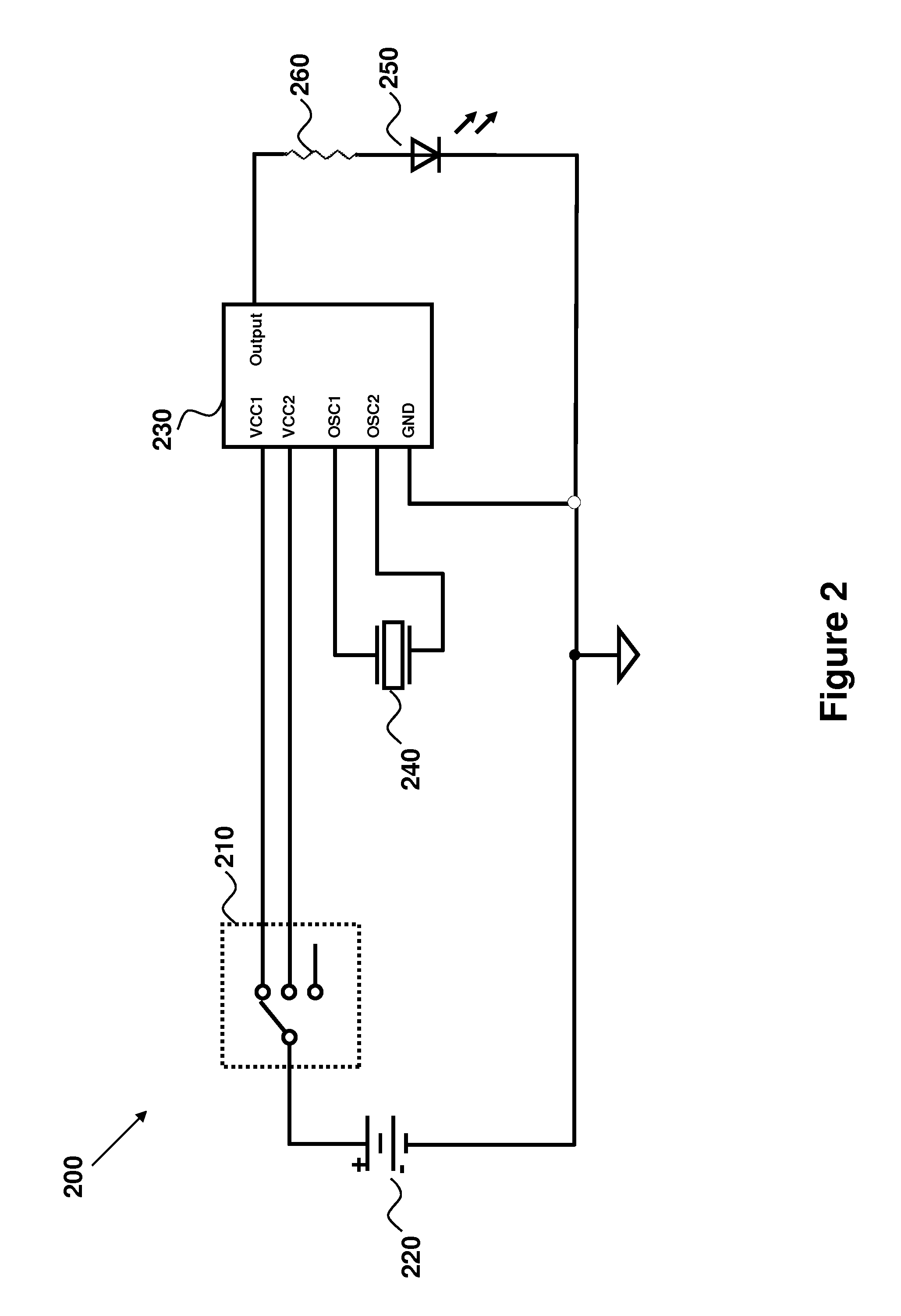
The present invention is related to a flameless candle circuit that includes an ASIC and a single-pole switch. The circuit is designed to provide a flickering signal to the LED in two modes: a first mode when the battery voltage is connected to the first power terminal of the ASIC and the second power terminal is not connected, and a second mode when the battery voltage is connected to both power terminals of the ASIC. The circuit can also be programmed to intermittently provide a flickering signal based on a slow timer. The technical effect of this invention is to provide a flameless candle circuit that can accurately control the flickering signal and can be programmed for different flickering patterns.

Problems solved by technology

Such a circuit may cause an LED to flicker, thereby creating an illusion of a flickering flame.
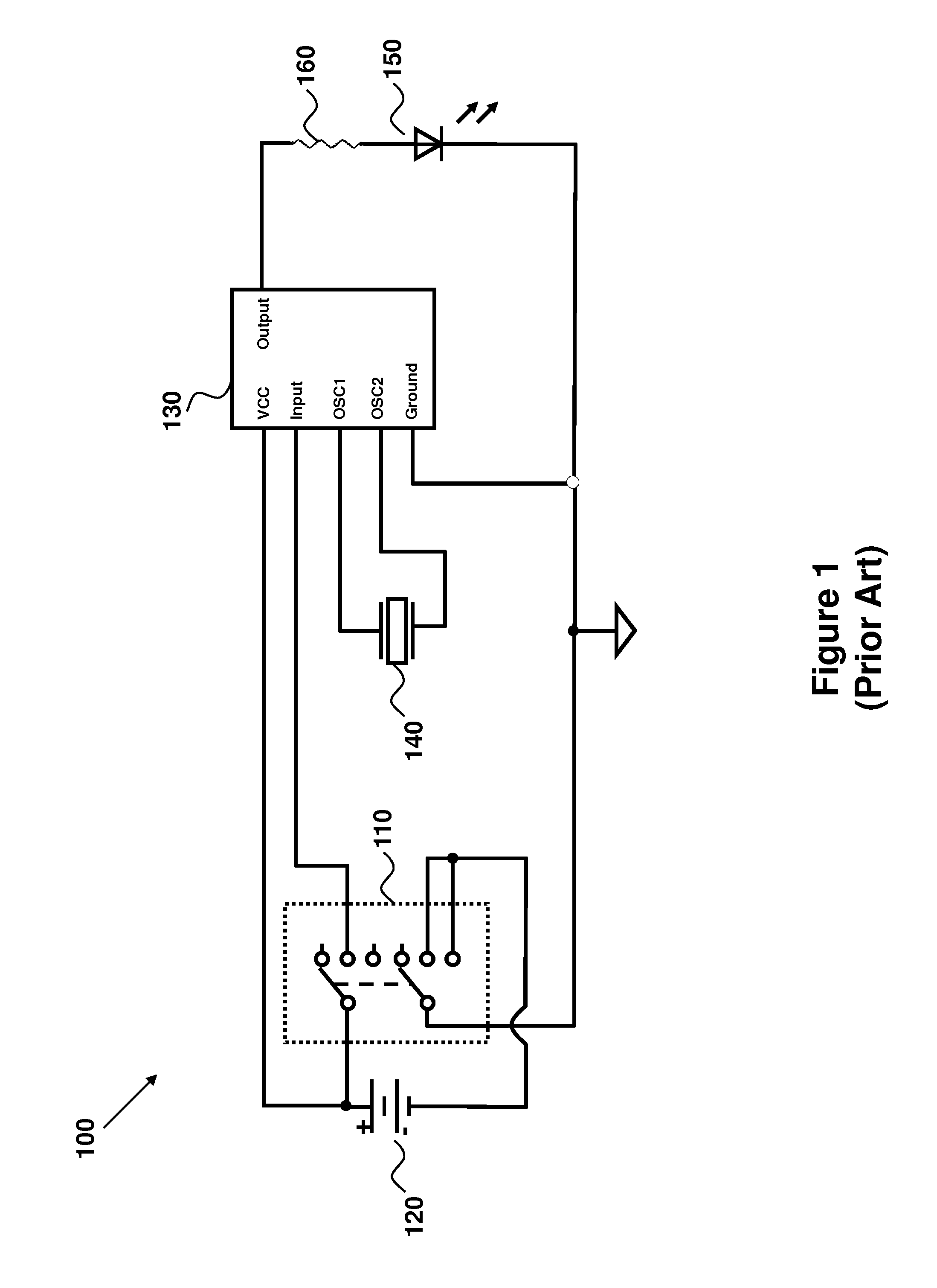
In addition to the part cost, the 2P3T switch 110 requires relatively complex wiring, thereby increasing material costs again.
Furthermore, such a component may take up more space on a printed-circuit board or in other dimensions.

Method used


Image

  • Flameless candle circuit with multiple modes
  • Flameless candle circuit with multiple modes
  • Flameless candle circuit with multiple modes

Examples


Embodiment Construction

[0035]FIG. 2 shows a schematic illustration of a flameless candle circuit 200, according to an embodiment of the present invention. The circuit 200 includes a single-pole, triple-throw switch 210, a battery 220, an application specific integrated circuit (“ASIC”) 230, an oscillator 240, an LED 250, and a resistor 260. The ASIC 230 includes the following pins or terminals: output, ground, oscillator 1 (“OSC1”), oscillator 2 (“OSC2). Also, instead of having only one power terminal like processor 130, the processor 230 has two power terminals—a first power terminal (“VCC1”) and a second power terminal (“VCC2”).

[0036]The circuit 200 generally operates in the following manner. The oscillator 240 regulates the timing functions of the ASIC 230. The ASIC 230 has an output that can provide a signal to the resistor 260 (e.g., current-limiting resistor) and the LED 250. The signal causes a current to flow through the LED 250, which then emits light. The switch 210 may be a single-pole switch. ...


PUM


Abstract

According to embodiments of the present invention, a flameless candle circuit includes an application-specific integrated circuit (“ASIC”) having a first power terminal, a second power terminal, and an output. The circuit also includes a light-emitting diode (“LED”) and a single-pole switch. The LED is configured to receive a signal from the output of the ASIC. The single-pole switch is configured to selectively provide the battery voltage to at least one of the first power terminal and the second power terminal. Additionally, the single-pole switch is configured to remove the battery voltage from both of the first power terminal and the second power terminal to turn the ASIC off. The ASIC is configured to drive the LED in a first mode when the battery voltage is provided to the first power terminal. The ASIC is also configured to drive the LED in a second mode when the battery voltage is provided to the second power terminal.

Description

BACKGROUND OF THE INVENTION[0001]Generally, the present application relates to flameless candle circuits. Particularly, the present application relates to flameless candle circuits that cause light emitting diode(s) (“LED”) to generate light in two or more different modes.[0002]Flameless candles may include a circuit (e.g., one or more circuits or sub-circuits) that drives one or more LEDs to generate light. Such a circuit may cause an LED to flicker, thereby creating an illusion of a flickering flame. The circuit may also include a timer that can automatically turn the LED off after a period of time. The timer may also turn the LED back on after another period of time.[0003]FIG. 1 shows a schematic illustration of a prior art flameless candle circuit 100. The circuit 100 has a double-pole triple-throw switch (“2P3T switch”) 110, a battery 120, an application specific integrated circuit (“ASIC”) 130, an oscillator 140, an LED 150, and a resistor 160.[0004]The circuit 100 generally o...

Claims


Application Information

Patent Timeline
Patent Type & Authority Patents(United States)
IPC IPC(8): F21V35/00H05B44/00
CPCF21S10/04F21L4/00H05B33/0845F21V23/00F21K99/00Y02B20/42F21V23/04Y02B20/346H05B45/10
Inventor SAGNA, BENJAMINBOUCHER, FREDERIC
Owner STERNO HOME INC
Learn More