
Sorting apparatus and method utilizing a mechanical diverter

a mechanical diverter and sorting apparatus technology, applied in sorting and other directions, can solve the problems of reducing the perceived value of the diverter, reducing the accuracy of the ejection operation, and reducing the ejection accuracy

Inactive Publication Date: 2014-03-04
KII TEKU INC
View PDF12 Cites 42 Cited by
  • Summary
  • Abstract
  • Description
  • Claims
  • Application Information

AI Technical Summary

Benefits of technology

[0009]One aspect of the present invention relates to a sorting apparatus for separating articles in a product stream, and which includes an endless belt conveyor configured to launch articles from the product stream in a first trajectory; an inspection station coupled to the product stream and operable to provide a routing signal based on inspection of the product stream; and a diverter comprising a launching block having a concave surface, and located in downstream relation relative to the inspection station, and controlled by the routing signal, and wherein the diverter has a retracted position where articles extend their travel in the first trajectory, and an extended position where articles interact with the diverter in a gliding manner along the concave surface to effectively launch the articles into a second trajectory.
[0012]Still another aspect of the present invention relates to a sorting apparatus which includes a conveyor for transporting a multiplicity of articles in a continuous product stream, and which includes acceptable and unacceptable articles, and foreign material, and which further propels the product stream into a first path of travel; an inspection station positioned along the first path of travel, and wherein the inspection station visually inspects the product stream so as to identify the respective acceptable articles, unacceptable articles and foreign material, and further generates a plurality of routing signals following the inspection of the product stream; and a diverter assembly located downstream of the inspection station, and in spaced relation relative to the conveyor, and wherein the diverter assembly is controlled by the plurality of routing signals supplied by the inspection station, and further has a first and second plurality of selectively moveable launching blocks, and wherein the second plurality of launching blocks are located downstream of, and in substantially gravitationally feeding alignment with, the respective first plurality of selectively moveable launching blocks, and wherein the individual moveable launching blocks of the first and second plurality each have a first, retracted position, and a second, extended position, and wherein, when the individual launching blocks of the first and second plurality are both in the retracted position, the individual articles moving along in the product stream move along a second path of travel; and wherein when the individual moveable launching blocks of the first plurality are in the extended position, the individual articles moving along in the product stream move along a third path of travel; and wherein when the individual moveable launching blocks of the first plurality are in a retracted position, and the second plurality of launching blocks are in an extended position, the individual articles travelling along in the product stream move in a fourth path of travel, and wherein the second, third and fourth paths of travel effect the sorting of the articles in the product stream.

Problems solved by technology

Thus, the undesirable articles are dislodged from their course of travel and caused to take an alternate path, removing them from the product stream.
In addition, mechanical diverters are more prone to undesirably bruised articles during a diversion.
Unfortunately, the striking action of the paddle upon the article during its course of travel has the potential to bruise the articles, thereby reducing their perceived value.
However, it would appear that a flexible finger would also decrease the accuracy of the ejection operation by nature of its flexibility.
In addition, the art does not teach the combination of utilizing both an air ejection device, and mechanical diversion in a single sorter arrangement.

Method used


Image

  • Sorting apparatus and method utilizing a mechanical diverter
  • Sorting apparatus and method utilizing a mechanical diverter
  • Sorting apparatus and method utilizing a mechanical diverter

Examples


Embodiment Construction

[0029]This disclosure of the invention is submitted in furtherance of the constitutional purposes of the U.S. Patent Laws “to promote the progress of science and useful arts” (Article 1, Section 8).

First Form

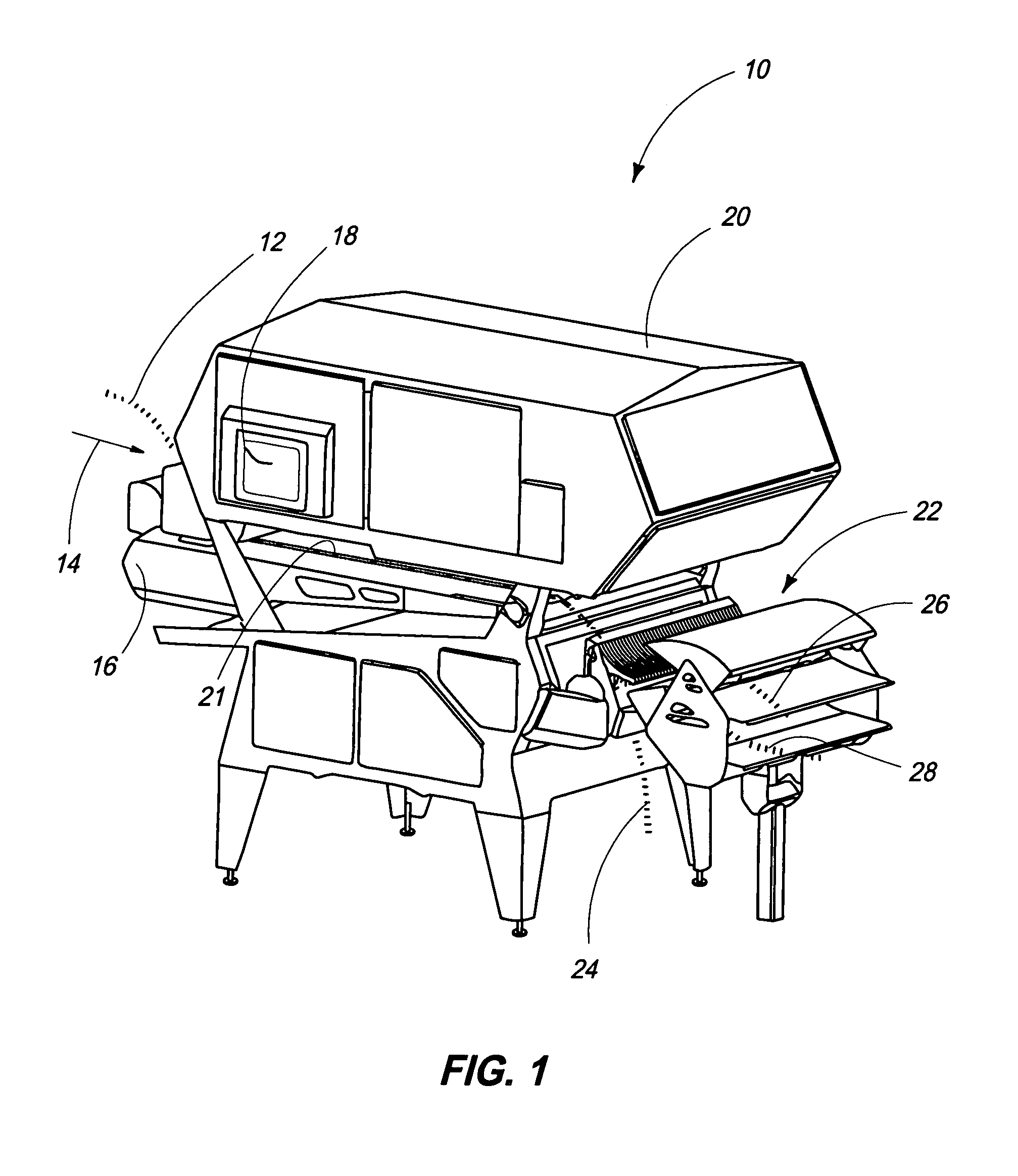
[0030]Referring now to FIG. 1, a first form of an apparatus for sorting articles, and which utilizes a mechanical diverter is shown, and is generally identified by the numeral 10 and will be referred to as a “sorter” in this disclosure. The sorter 10 is installed in a processing line adjacent to other equipment in a continuous production system. The apparatus 10 is located in a processing line at a strategic location where the quality of each article is ascertained and is routed for further processing.

[0031]A stream of articles, or incoming product stream 12 is introduced at an infeed end of the sorter 10. In practice, the product stream 12 may be composed of any article of manufacture or production, and often includes both desirable articles which meet the specification of qual...


PUM


Abstract

The present invention is an apparatus and method for sorting foreign material and undesirable articles from a product stream. A mechanical diverter having a concave shape is responsive to an inspection station coupled to the product stream. The mechanical diverter is employed to effectively launch or otherwise redirect undesirable articles in an alternate path. In addition, an air ejector in one form of the invention is provided and is responsive to the inspection station and is employed to dislodge foreign material from the product stream.

Description

RELATED PATENT DATA[0001]This patent application is a Continuation-In-Part of U.S. patent application Ser. No. 12 / 383,199, and which was filed on Apr. 19, 2009.TECHNICAL FIELD[0002]The present invention relates to a sorting apparatus and method, and more specifically to a sorting apparatus and method for separating articles in a product stream using a mechanical diverter responsive to a machine vision system. The present invention also includes, in one form of the invention, a combination of a sorting apparatus that uses an air ejector for foreign material removal and a mechanical diverter for redirecting undesirable articles from a product stream.BACKGROUND OF THE INVENTION[0003]Sorting methods and machines have been known and practiced for many years in the production of goods including comestible articles. The machines found in the art include types that utilize reflecting electromagnetic radiation in the form of light to determine the optical reflective characteristics of the ar...

Claims


Application Information

Patent Timeline
Patent Type & Authority Patents(United States)
IPC IPC(8): B07C5/06
CPCB07C5/363B07C5/362
Inventor JONES, PETER T.HOFFMAN, PHILIP L.HALMBERGER, HANS G.MCGARVEY, KENRUFF, JAMESLEMKE, MIKEREARDON, TIMOTHY
Owner KII TEKU INC
Learn More