
Method for printed circuit board trace characterization

a technology of printed circuit boards and trace characterization, which is applied in the direction of individual semiconductor device testing, instruments, nuclear elements, etc., can solve the problems of degrading communication capability, reducing communication efficiency, and traditional methods that have not been successful, and achieves fast, easy and economical methods. , the effect of facilitating the utilization of the same test coupon structur

Active Publication Date: 2014-02-25
TELEDYNE LECROY
View PDF5 Cites 2 Cited by
  • Summary
  • Abstract
  • Description
  • Claims
  • Application Information

AI Technical Summary

Benefits of technology

[0013]It is an object of this invention to preferably provide a fast, easy and economical method for providing PCB trace characteristics measurements. It is further an object of this invention to preferably facilitate the utilization of the same test coupon structures and probing arrangements as recommended by SE2DIL. It is a further object to preferably provide an alternate calculation method capable of providing the same intended result of SE2DIL along with additional PCB trace characteristics.
[0020]The inventors have further determined that with a transmission line model consisting of frequency dependent reflection-coefficient, loss, and delay, the reflection-coefficient can be isolated by conversion of a one-port modal measurement to the time-domain and restricting the length of the time-domain response. Once the reflection-coefficient is isolated, loss and delay measurements are easily obtained and the DUT may be fully characterized.
[0021]The measurements made of these transmission line models may be optionally converted to single-ended measurements. The measurements facilitate the determination of trace impedance in mixed-mode or single-ended and facilitate loss and electrical length measurements. Fitting is performed to further convert loss measurements to metrics that provide loss per frequency, loss per square-root of frequency, and further to losses that are frequency and length dependent. The method makes similar provisions for electrical length and propagation velocity which facilitates the determination of other important PCB and PCB trace characteristics.
[0022]The present method provides for refining the measurements made through the fitting of the measurement to a single-ended model of the DUT enabling the matching of the calculated DUT to the measurements in a least-squares error sense. This fitting also allows metrics, such as variance, that provide metrics on the quality of the measurement and the quality of the assumptions made regarding symmetry, reciprocity and lack of mode-conversion assumed in the model.

Problems solved by technology

When elements in the path of a high-speed signal have different characteristic impedances, reflections occur which may degrade communications.
When a trace is excessively lossy signals may be attenuated at high frequencies and again, the communications capability is degraded.
These traditional methods have been less successful as of late, especially when the traces are to be used with high speed data transfers.
There are several problems with this situation.
First, for many PCB manufacturers, high-frequency electrical characteristics are a domain of engineering that is foreign to them.
Next, the measurement of high-frequency characteristics are difficult and often time consuming.
Finally, the equipment needed to perform these measurements is very expensive.
VNA instruments tend to be more expensive and less familiar to PCB manufacturers.
Because of the ability to measure loss using a single single-ended two-port measurement, the method is relatively fast and requires only a two-port VNA or TDR instrument, which is really the key aspect as the measurements facilitated by SE2DIL could be made easily with a four-port instrument and a four-port measurement test structure, albeit with more test instrument cost, complexity and time.
One problem with the SE2DIL method is that it is somewhat of an adhoc, algorithmic approach.
It has been found that there are many parameters in the algorithm that must be tweaked to get good repeatable results and that there are dependencies on characteristics of measurement instruments that are not entirely understood.

Method used


Image

  • Method for printed circuit board trace characterization
  • Method for printed circuit board trace characterization
  • Method for printed circuit board trace characterization

Examples


Embodiment Construction

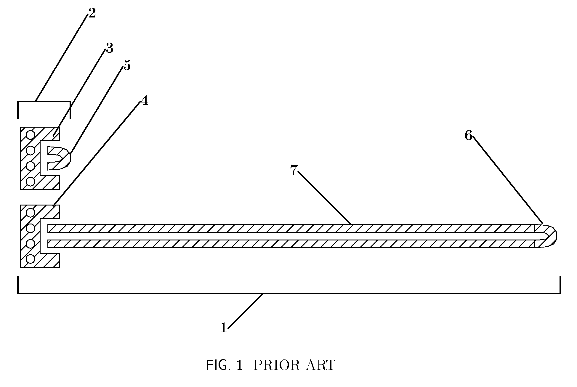
[0034]FIG. 1 shows elements of an exemplary test-coupon that may be employed for a PCB trace characterization measurement. It shows a trace characterization structure [1] and a termination characterization structure [2]. Both structures [1],[2] are intended to be substantially similar in that each contains a probing structure [3], [4] and a termination structure [5], [6] except that the trace characterization structure [1] contains a differential trace element [7] which is the DUT and is the element to be characterized.

[0035]The intent of the structures in FIG. 1 is that measurements are obtained for the trace characterization structure [1] and for the termination characterization structure [2] by probing and measuring each one. Based on these measurements, one or more characteristics of the DUT may be obtained.

[0036]Assuming that the termination structures [5], [6] are substantially similar and that a good measurement can be made of the termination structure [5] by measuring at the...


PUM


Abstract

A method is provided which measures PCB trace characteristics from measurements of a PCB trace structure.

Description

FIELD OF THE INVENTION[0001]The present invention relates in general to the measurement of electrical characteristics of printed circuit boards, and more particularly to the testing of one or more characteristics required for traces that propagate high-speed signals as en-countered in serial data communications.BACKGROUND OF THE INVENTION[0002]The printed circuit board (PCB) is an element in many electronic products that contain electronic components. The PCB holds components and connects these components electrically through metal traces. In some applications, especially high speed serial data communications, high quality traces are required. Thus the characteristics of these metal traces must be measured and tested to ensure high quality.[0003]Until relatively recently, the determination PCB and PCB trace quality meant the determination of the ability to handle current or voltage and or electrical resistance. As of late, however, many high-speed PCB traces are tested for character...

Claims


Application Information

Patent Timeline
Patent Type & Authority Patents(United States)
IPC IPC(8): G01R31/26
CPCG01R31/2818G01R31/28
Inventor PUPALAIKIS, PETER JDOSHI, KAVIYESH
Owner TELEDYNE LECROY
Learn More