
In-water voltage gradient detector

a voltage gradient and detector technology, applied in the field of voltage gradient detectors, can solve the problems of inability to maintain, unsafe conditions in swimming pools, hot tubs, spas, etc., and achieve the effect of simplifying circuitry and less dependency

Active Publication Date: 2014-02-04
GSC TECHNOLOGY LLC
View PDF14 Cites 12 Cited by
  • Summary
  • Abstract
  • Description
  • Claims
  • Application Information

AI Technical Summary

Benefits of technology

The patent is about a device that can detect voltage gradients and provide a visual or audio alarm when there is a potential hazard. The device uses pairs of LEDs that are responsive to different polarities of voltage gradients, making it easy to monitor changes in voltage without needing to reorient it. The LEDs can also be programmed to different colors to indicate the direction of the voltage gradient. The device also includes a voltage limiter to protect the LEDs from damage from high voltages. Additionally, the device can use three sets of organized electrodes to detect voltage gradients in multiple directions.

Problems solved by technology

Electrical gradients in water can create risks of electrocution and electroshock drowning if an individual enters water in which a sufficiently strong voltage gradient is present.
Such hazardous conditions can occur in swimming pools, hot tubs, spas, and Jacuzzis which have improperly installed, poorly maintained, or otherwise faulty underwater lighting, heaters pumps, wiring, or other electrically operated equipment or appliances.
However, such circuit breakers may not be present in older facilities, which are also subject to greater risk due to deterioration over time of wiring for underwater equipment.
There are also possibilities of risk at locations in more open water, where voltage gradients may be present due to fallen electrical transmission lines, current leakage from boats, or other voltage sources.
The device appears to be limited to active use, and detects only AC voltages.
Furthermore, the device is described as having a typical battery life of 10 days, making it ill-suited for passively monitoring a location to provide warning of when a voltage gradient is present in the water at that location.

Method used


Image

  • In-water voltage gradient detector
  • In-water voltage gradient detector
  • In-water voltage gradient detector

Examples


Embodiment Construction

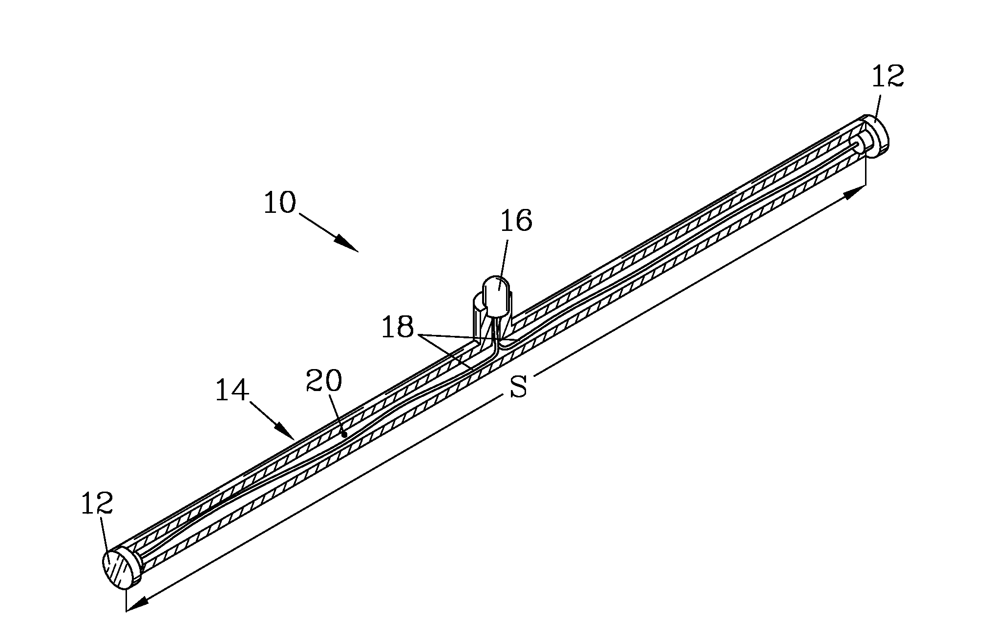
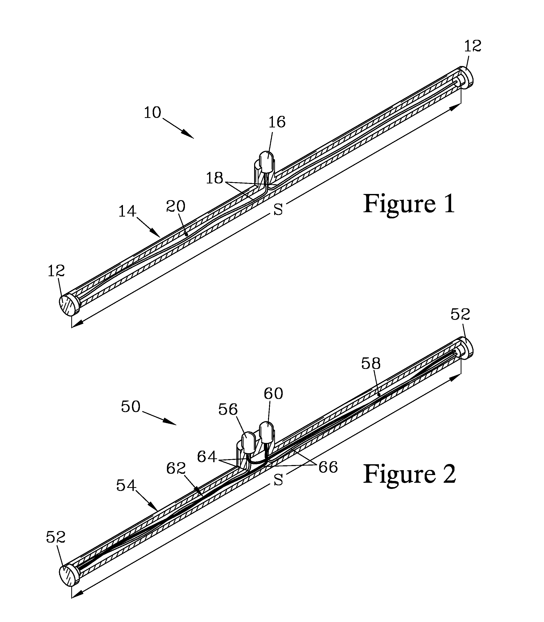
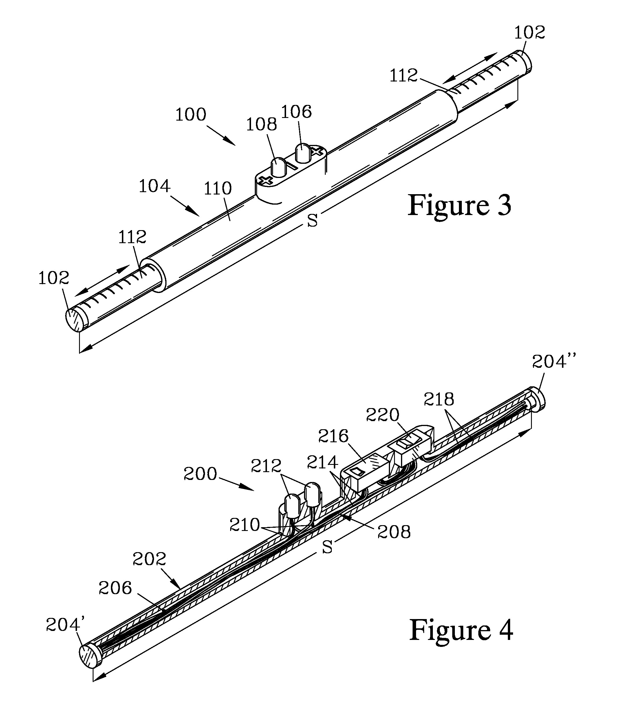
[0029]FIG. 1 is an isometric view of one embodiment of an in-water voltage gradient detector 10 of the present invention. For reasons discussed below, the gradient detector 10 has characteristics that make it suitable for providing notice to an individual when the voltage gradient in the direction measured is above a threshold level where an individual entering the water would be likely to be harmed by the voltage gradient. The device 10 has a pair of spaced apart electrodes 12 that are maintained at a separation S by a hollow spacer 14, to which the electrodes 12 are sealably attached.

[0030]An LED 16 resides between the electrodes 12, and is sealably attached to the spacer 14 such that its electrical contacts can be connected to the first pair of electrodes 12 by a pair of conductors 18. The sealable attachment of the electrodes 12 and the LED 16 to the spacer 14 serves to electrically isolate the electrodes 12 from each other, except for their connection through the LED 16 via the...


PUM


Abstract

A voltage gradient detector provides notice when a potentially hazardous voltage gradient is present in water, employing a pair of spaced-apart electrodes connected to an LED. The electrode spacing is selected such that, when exposed to a sufficiently large voltage gradient, the voltage between the electrodes causes activation of the LED. The LED can provide visual illumination, or can be a part of a switching device such as a photoMOS relay that in turn activates an alarm device such as an audible sounder or a high-intensity light. Sensitivity in multiple directions can be attained by employing a pair of LEDs between the electrodes, and by employing three pairs of electrodes and associated LED pairs, with the pairs of electrodes being spaced apart along orthogonal axes. The detector can be a passive monitor housed in a floating housing, or can be a handheld device with electrode pairs that are manually immersed.

Description

FIELD OF THE INVENTION[0001]The present invention provides a voltage gradient detector for providing notice of the presence in water of a voltage gradient greater than a specified strength.BACKGROUND OF THE INVENTION[0002]Electrical gradients in water can create risks of electrocution and electroshock drowning if an individual enters water in which a sufficiently strong voltage gradient is present. Such hazardous conditions can occur in swimming pools, hot tubs, spas, and Jacuzzis which have improperly installed, poorly maintained, or otherwise faulty underwater lighting, heaters pumps, wiring, or other electrically operated equipment or appliances. Currently, protection against electrocution and electroshock drowning hazards in such facilities depends mainly upon the use of GFCI (ground fault circuit interrupter) circuit breakers being installed on AC power lines. However, such circuit breakers may not be present in older facilities, which are also subject to greater risk due to de...

Claims


Application Information

Patent Timeline
Patent Type & Authority Patents(United States)
IPC IPC(8): G01R31/00
CPCG08B21/02G01R19/0084G01R15/22G01R31/00G01R19/28G01R31/30G01R19/16576G01R19/155G01R1/06G01R29/12G08B5/36G08B7/06
Inventor CARGILL, III, GEORGE, S.
Owner GSC TECHNOLOGY LLC
Learn More