Latching mechanism

a technology of latching mechanism and latching plate, which is applied in the field of latches, can solve the problems of higher load on latching plate, and achieve the effects of large take-up requirements, higher load, and higher load

Active Publication Date: 2014-02-04
AVIBANK MFG
View PDF4 Cites 0 Cited by
  • Summary
  • Abstract
  • Description
  • Claims
  • Application Information

AI Technical Summary

Benefits of technology

[0002]It is an object of this invention to provide an aircraft latch which has the capability of drawing together larger structures over relatively long distances, securely closing and locking so the aircraft latch cannot be opened accidentally during service or the like and which meets requirements for high loading, spatial limitations and meets kinematic requirements. These objects are met by combining an over-center link mechanism with a worm-gear drive mechanism. The apparatus comprises a handle member which both opens the latch but which also drives a gearing system to complete the latch opening process to achieve the large take-up requirements. The presently disclosed device draws larger structures together over longer distances, preloads the system to higher loads, and carries higher loads.

Problems solved by technology

This is particularly true when the latch must draw together larger structures over longer distances, and the latch is subjected to higher loads.

Method used


Image

  • Latching mechanism
  • Latching mechanism
  • Latching mechanism

Examples


Embodiment Construction

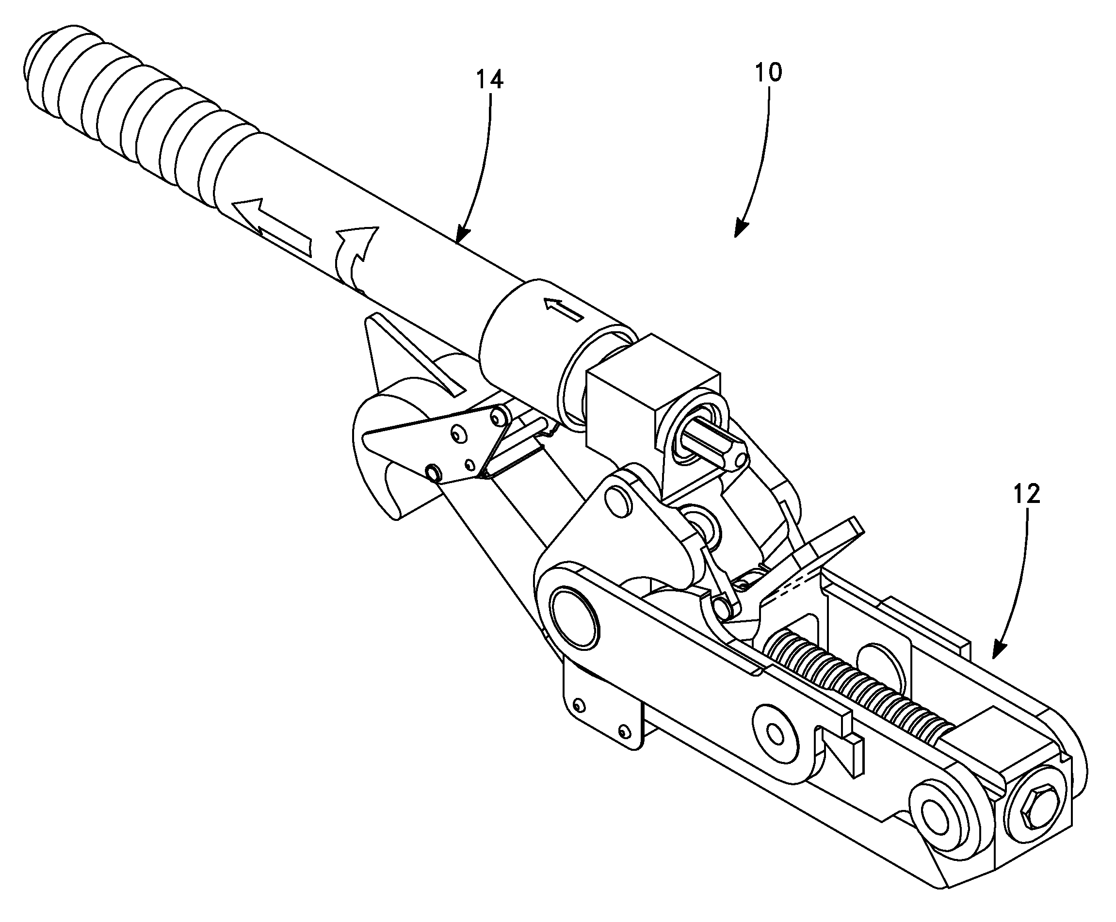
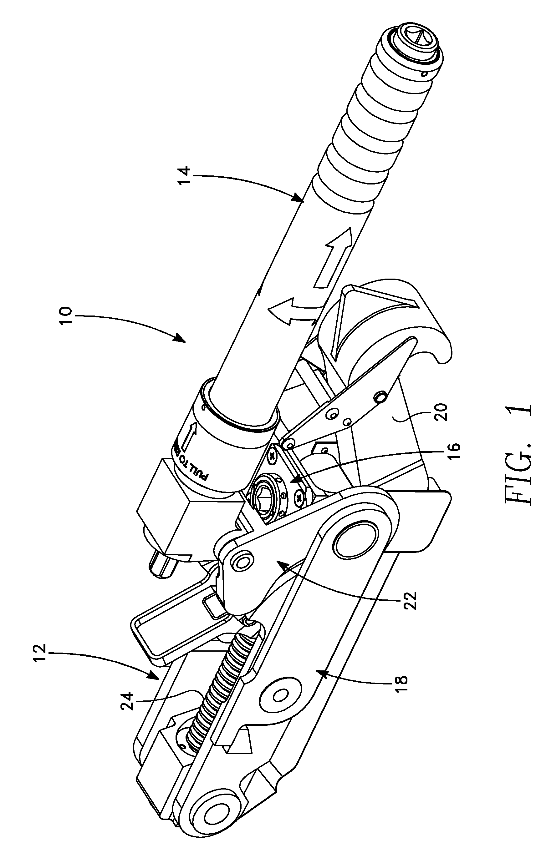
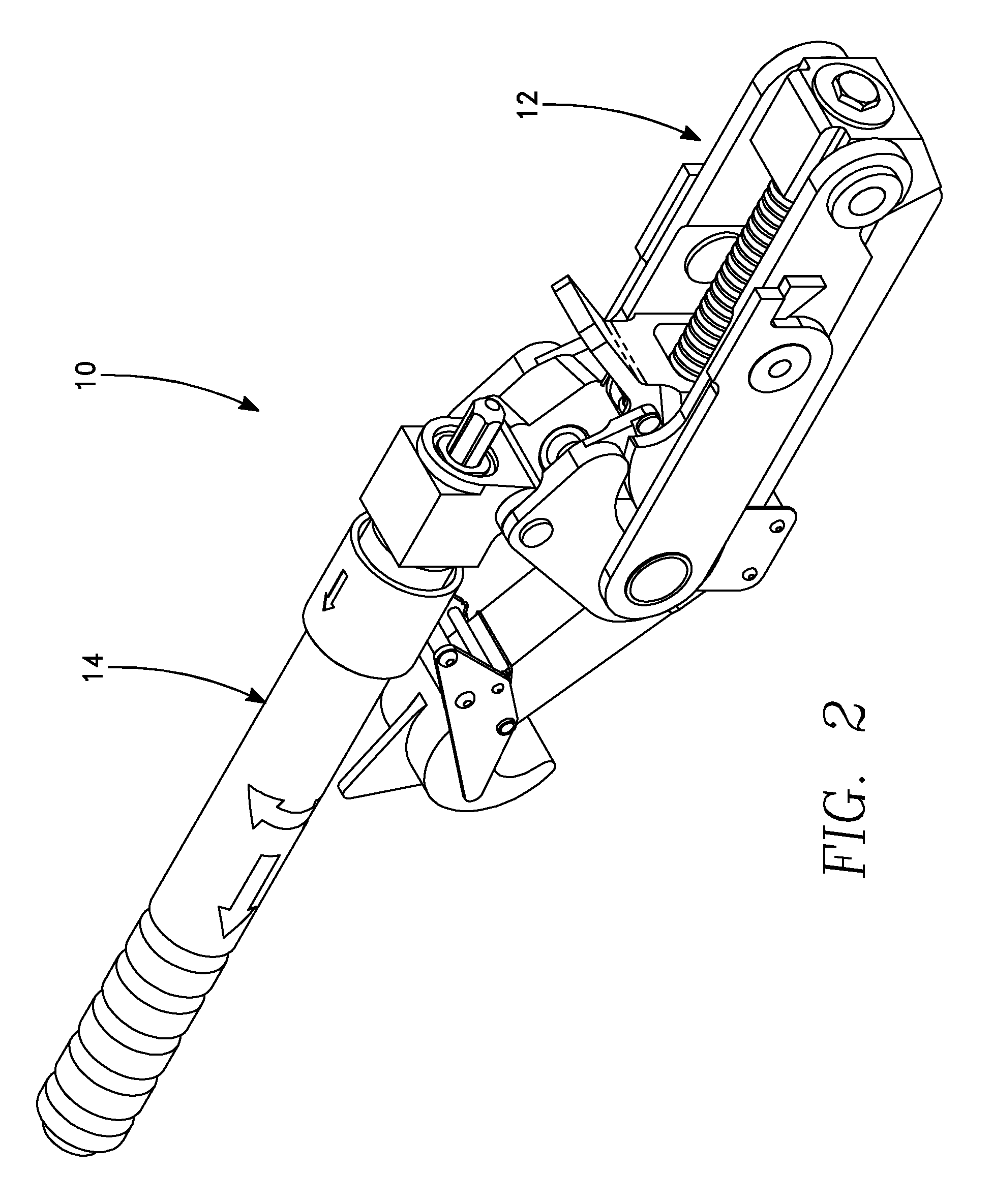
[0013]Referring now to the Figures, an embodiment of the disclosed latching mechanism 10 is depicted in FIG. 1. The latching mechanism 10 generally comprises two components, being a latch assembly 12 and a handle member 14. Latch assembly 12 generally comprises a gear housing 16, an over-center link assembly 18, a latch body 20, cam member 22, and a spindle 24. Referring to FIG. 3, in indicating various directions within the following description, the front of the latching mechanism 10 is indicated as F, the rear is indicates as R, the bottom is indicated as B, and the top indicated as T. However, it is to be appreciated that the latching mechanism 10 is operational in any relative position and the above designations are provided for reference purposes only.

[0014]Gear housing 16 comprises a pair of intermeshing bevel gears 26, 28 which are generally mounted at right angles to one another. The first bevel gear 26 has means for engagement with the spindle 24, such as a rearward facing...


PUM


Abstract

An aircraft latch utilizes a spindle in combination with an over-center linkage assembly to impart linear motion to a hook member, causing the hook member to either disengage or engage a keeper member on the adjacent structure. The over-center linkage and the spindle are operated by different and independent operations of a handle member. Specifically, the over-center linkage is moved from a stored position, in which the two link members are in end-to-end axial alignment, to a position in which the two link members are no longer in end-to-end axial alignment. This movement is caused by pivoting the handle member from a position in which the longitudinal axis of the handle member is parallel to the axis of the aligned link members, to a second position in which the handle member is pivoted at least ninety degrees. This pivoting motion, which may be accompanied by other actions, such as releasing a trigger, causes the two link members to pivot with respect to each other, or “break”. Once the two link member have broken from the over-center position, the handle is then rotated, causing the spindle to rotate, and thereby imparting a generally linear motion to the hook member, causing the hook to disconnect from the keeper member. The hook member is caused to engage the keeper member by reversing these steps.

Description

BACKGROUND OF THE INVENTION[0001]The invention relates to latches; and more particularly, to aircraft latches. Latches are used on the exterior surfaces of aircraft where it is important that the latch present a flush surface with the aircraft body and indicate when the latch is in a locked or unlocked position. Such latches normally cooperate with a keeper or locking pin on an opposing surface for engaging the latch. It is important that such latches be securely and tightly latched especially when subjected to high vibrations and rattling. This is particularly true when the latch must draw together larger structures over longer distances, and the latch is subjected to higher loads.SUMMARY OF THE INVENTION[0002]It is an object of this invention to provide an aircraft latch which has the capability of drawing together larger structures over relatively long distances, securely closing and locking so the aircraft latch cannot be opened accidentally during service or the like and which ...

Claims


Application Information

Patent Timeline
Patent Type & Authority Patents(United States)
IPC IPC(8): E05C5/00
CPCE05C19/14B64D29/06Y10T292/092Y10T292/0915Y10T292/0913Y10T292/0914
Inventor BAIC, ZELJKO
Owner AVIBANK MFG
Why Eureka
Try Eureka