
Method for multiple processor system-on-a-chip hardware and software cogeneration

a technology of hardware and software, applied in the direction of electrical/magnetic computing, instruments, analogue processes for specific applications, etc., can solve the problems of limiting the flexibility of the soc designer to customize the soc, the manual portion of the soc design process is error-prone, and the work can be substantial,

Active Publication Date: 2014-01-28
CADENCE DESIGN SYST INC
View PDF31 Cites 40 Cited by
  • Summary
  • Abstract
  • Description
  • Claims
  • Application Information

AI Technical Summary

Benefits of technology

The SSI flow of this patent allows users to easily describe the components and their interfaces without needing a specific protocol. This makes it easy to connect components in a flexible way without needing to modify the hardware or software tools. Its main technical effect is that it provides a flexible and efficient way of incorporating new components and interconnects in a system.

Problems solved by technology

Each IP block can be quite complex and can do substantial amounts of work both with and without predetermined cycle by cycle interaction off the SOC.
However, an SOC designer still has to manually instantiate the reused IP blocks and manually create the interconnects between the IP blocks.
This manual portion of the SOC design process is error-prone, time-inefficient, and costly.
Each of these requirements limits the flexibility of the SOC designer to customize the SOC.
Therefore, the SOC designer must sacrifice flexibility and customization for the decreased time-to-market offered by the platform-specific design environment.
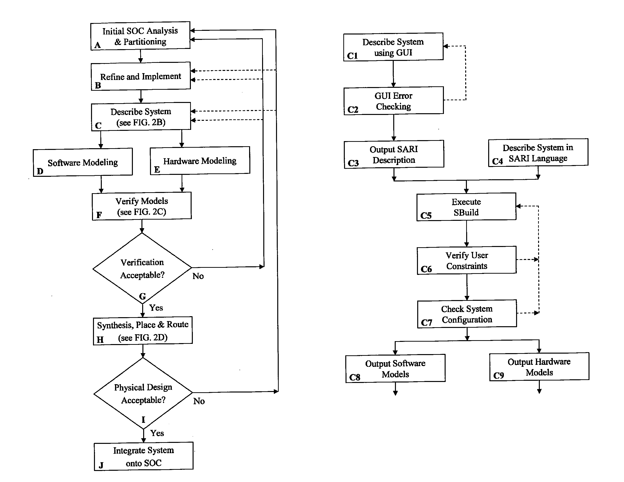
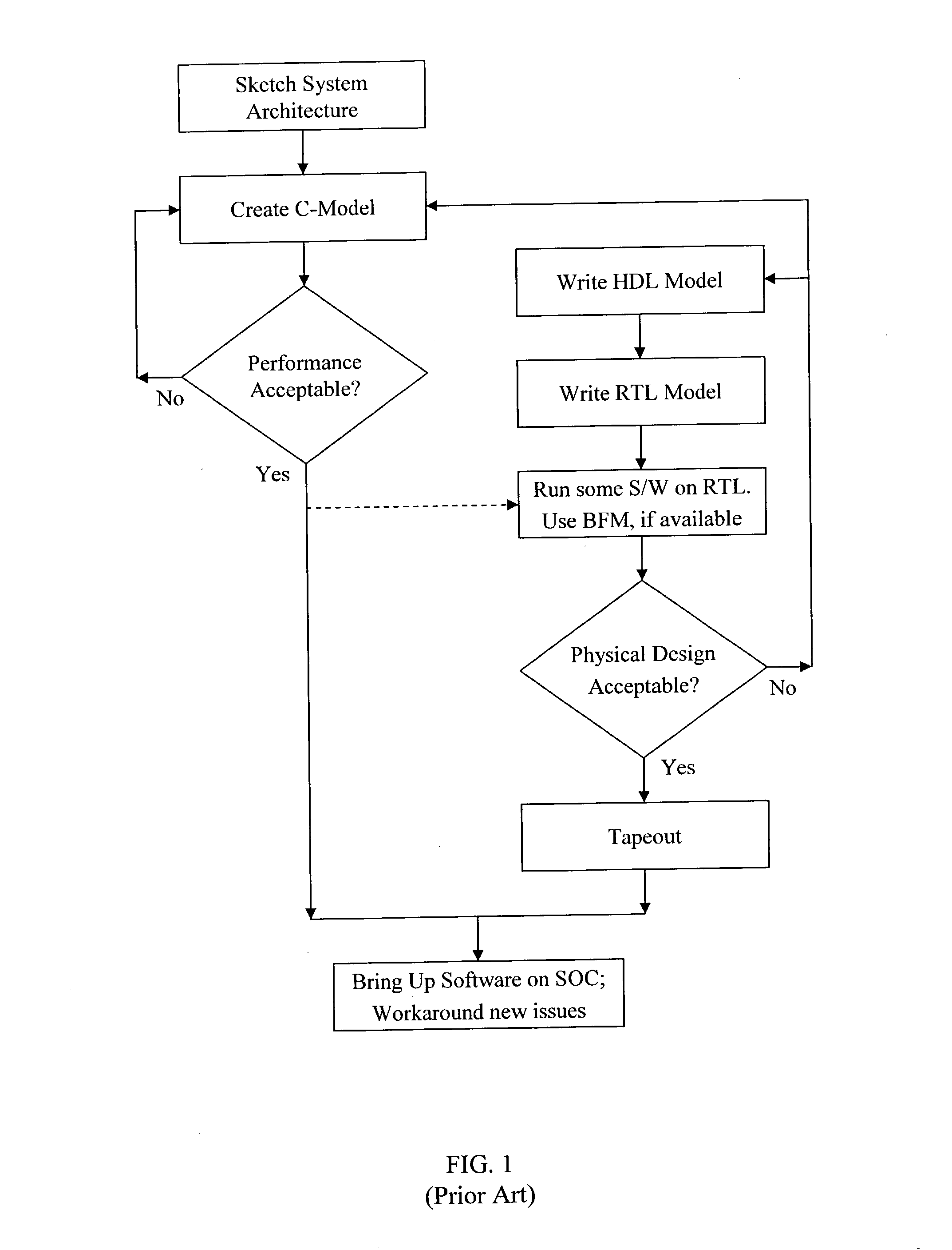
The feedback loop between the final physical design and the architecture is not a closed loop and any iterations made require many manual changes to different models and tools and is therefore extremely error-prone.
This newer generation design flow is equally as inefficient as the typical SOC design flow of FIG. 1 because, even though design of components can be reused, the system model must be manually rewritten to incorporate the components and to redesign the interconnects for each design iteration.

Method used


Image

  • Method for multiple processor system-on-a-chip hardware and software cogeneration
  • Method for multiple processor system-on-a-chip hardware and software cogeneration
  • Method for multiple processor system-on-a-chip hardware and software cogeneration

Examples


Embodiment Construction

[0020]The present invention will now be described in detail with reference to the drawings, which are provided as illustrative examples of the invention so as to enable those skilled in the art to practice the invention. Notably, the figures and examples below are not meant to limit the scope of the present invention. Moreover, where certain elements of the present invention can be partially or fully implemented using known components, only those portions of such known components that are necessary for an understanding of the present invention will be described, and detailed descriptions of other portions of such known components will be omitted so as not to obscure the invention. Further, the present invention encompasses present and future known equivalents to the known components referred to herein by way of illustration. The attached Appendices form part of the present disclosure and are incorporated herein by reference in their entirety and for all purposes.

[0021]The design and...


PUM


Abstract

An automated system-on-chip (SOC) hardware and software cogeneration design flow allows an SOC designer, using a single source description for any platform-independent combination of reused or new IP blocks, to produce a configured hardware description language (HDL) description of the circuitry necessary to implement the SOC, while at the same time producing the development tools (e.g., compilers, assemblers, debuggers, simulator, software support libraries, reset sequences, etc.) used to generate the SOC software and the diagnostics environment used to verify the SOC.

Description

FIELD OF THE INVENTION[0001]The present invention generally relates to the design of integrated circuits. More specifically, the present invention relates to a method for the automatic cogeneration of System-On-Chip (SOC) hardware and software from a single source description.BACKGROUND OF THE INVENTION[0002]The integrated circuit System-On-Chip (SOC) field has arisen as the amount of digital logic placed on a single semiconductor chip has substantially exceeded the amount of digital logic required by a single functional element. SOC technology uses the increased capacity of modern integrated circuits to create separate functional elements, or Intellectual Property (IP) blocks, on the same semiconductor chip. The separate IP blocks are connected and interconnected to satisfy the designer's system-level requirements. Each IP block can be quite complex and can do substantial amounts of work both with and without predetermined cycle by cycle interaction off the SOC. The IP blocks can a...

Claims


Application Information

Patent Timeline
IPC IPC(8): G06F9/45G06F17/50
CPCG06F17/505G06F2217/86G06F17/50G06F30/327G06F2117/08
Inventor EZER, GULBIN AYSEKONAS, PAVLOSANDREWS, JOHN BARRETTCHOU, STEPHEN WEILONG, EILEEN MARGARET PETERSEVANS, MARC ALAN
Owner CADENCE DESIGN SYST INC
Learn More