Optical transmission module, electronic instrument, method for assembling optical transmission module, and optical transmission method

a technology of optical transmission module and optical transmission module, which is applied in the field of optical transmission module, electronic instrument, method for assembling optical transmission module, optical transmission method, etc., can solve the problems of insufficient low profile, low profile of electronic instrument, and difficult to establish a balance between bending property and transmission characteristic for data transmission. , to achieve the effect of low profil

Inactive Publication Date: 2014-01-28
ORMON CORP
View PDF18 Cites 0 Cited by
  • Summary
  • Abstract
  • Description
  • Claims
  • Application Information

AI Technical Summary

Benefits of technology

[0013]In the techniques disclosed in Patent Documents 1 and 2, the repeated bending durability is improved by controlling the elastic modulus and thickness of the resin material layer in the flexible printed circuit board. However, in the flexible printed circuit board dedicated to the bending, it is necessary to establish impedance matching between the boards, and it is difficult to establish a balance between the bending property and a transmission characteristic for data transmission. Even if optical wiring is applied to the techniques disclosed in Patent Documents 1 and 2, it is not necessary to establish the impedance matching.
[0052]Therefore, the optical transmission module can be assembled to reduce the production cost using the same equipment for the usual optical transmission module in which the optical transmission unit and the optical reception unit are disposed in the same surface as the optical transmission path.

Problems solved by technology

However, in the flexible printed circuit board dedicated to the bending, it is necessary to establish impedance matching between the boards, and it is difficult to establish a balance between the bending property and a transmission characteristic for data transmission.
When the techniques disclosed in Patent Documents 1 and 2 are applied to the optical transmission module, a bending limit radius of the optical transmission path restricts the low profile of the sliding type mobile telephone, and unfortunately the low profile can insufficiently be achieved. FIG. 23 is a side view illustrating a configuration in which the techniques disclosed in Patent Documents 1 and 2 are applied to the optical transmission module.
However, cost increases because an optical path is converted by a combination of the plurality of mirrors in order to avoid the bending of the optical transmission path.
However, at this time, because most of an area of the optical transmission path is in contact with the electric transmission path, a mechanical load caused by friction with the electric transmission path is generated in the optical transmission path in addition to a stress caused by the bending.
In the optical transmission path in which the stress is generated near the bending portion bent with the bending limit radius, when a breakage is generated by the friction with the electric wiring, the fracture may be generated from the breakage.

Method used


Image

  • Optical transmission module, electronic instrument, method for assembling optical transmission module, and optical transmission method
  • Optical transmission module, electronic instrument, method for assembling optical transmission module, and optical transmission method
  • Optical transmission module, electronic instrument, method for assembling optical transmission module, and optical transmission method

Examples


modification 1

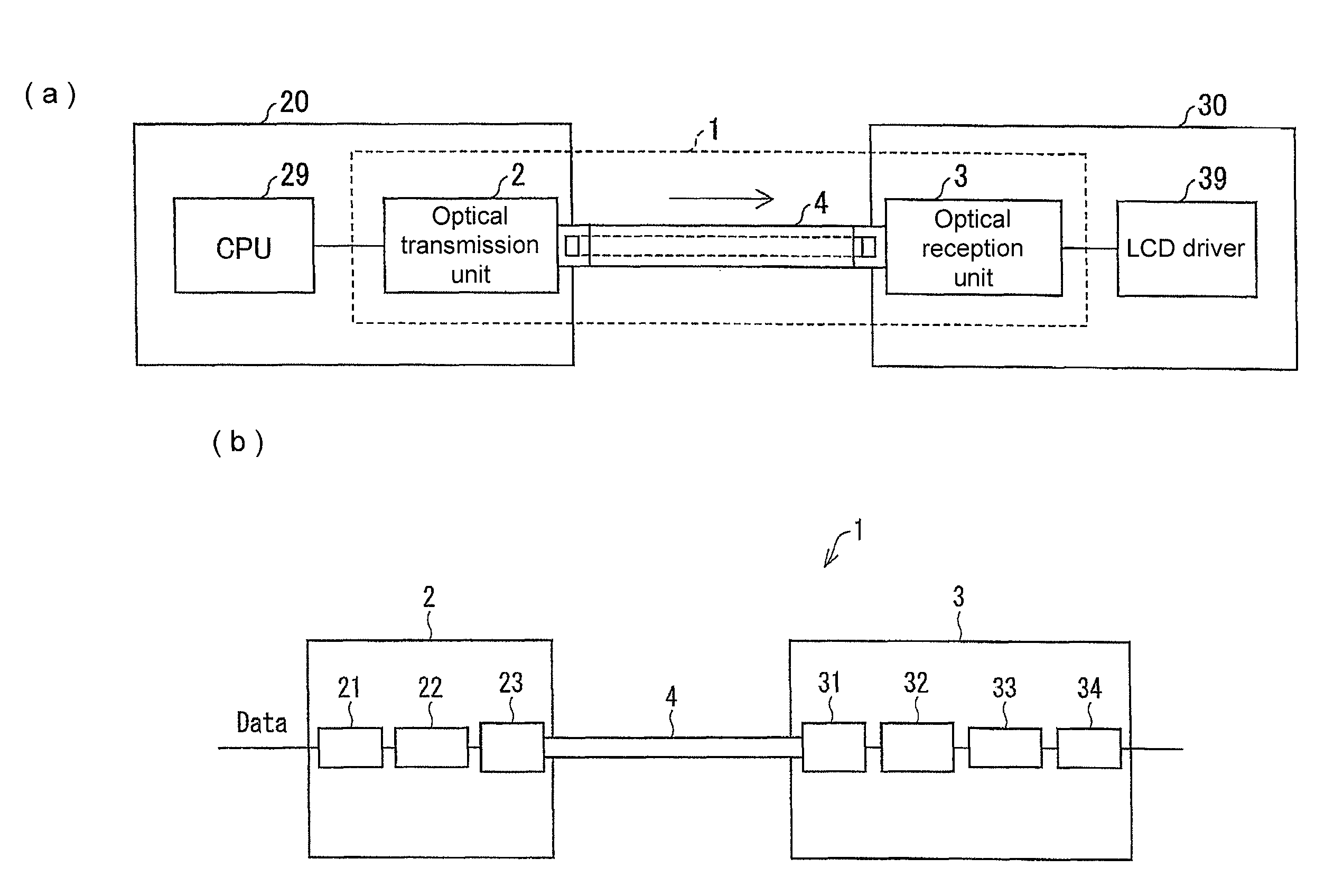
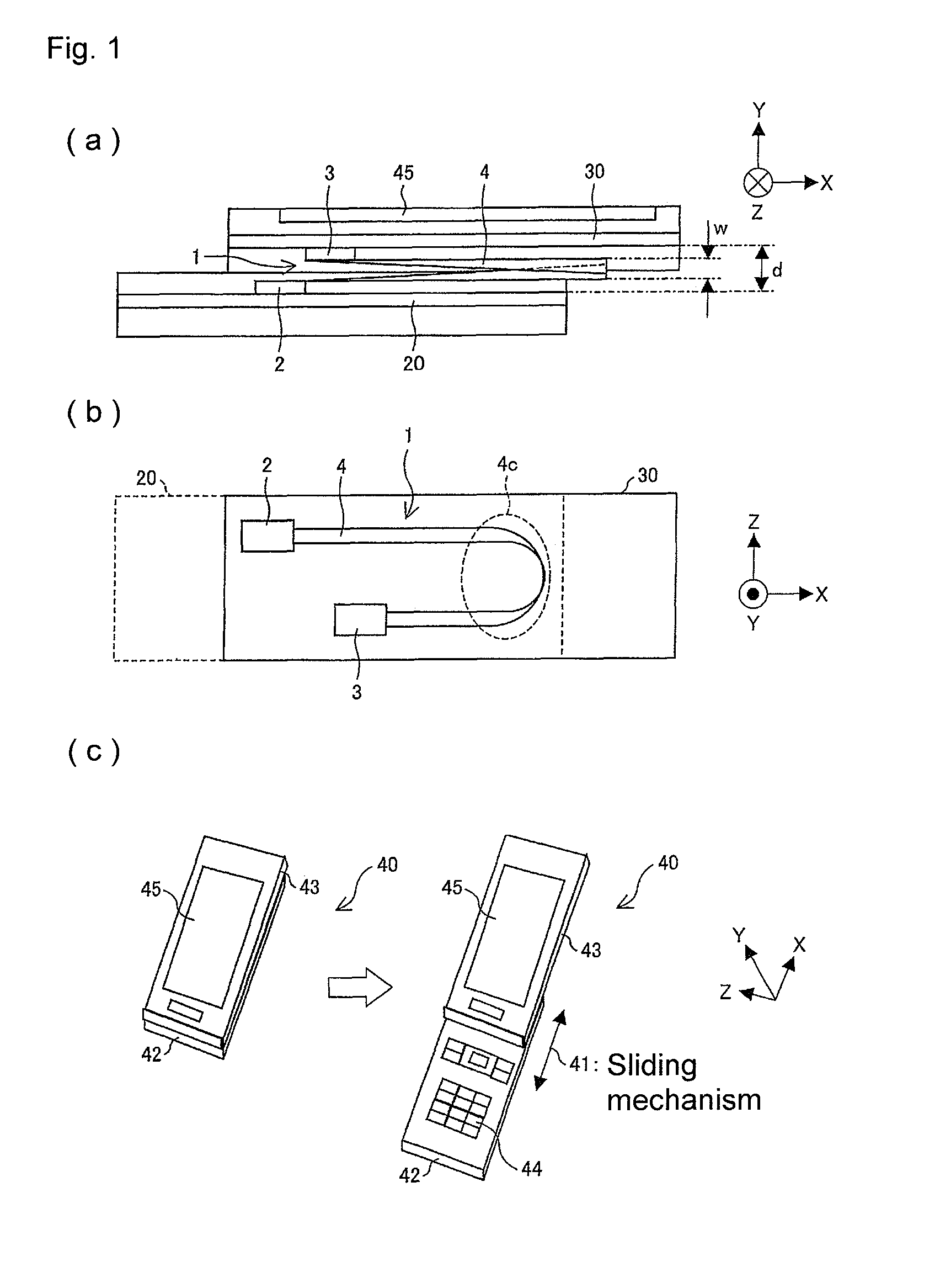
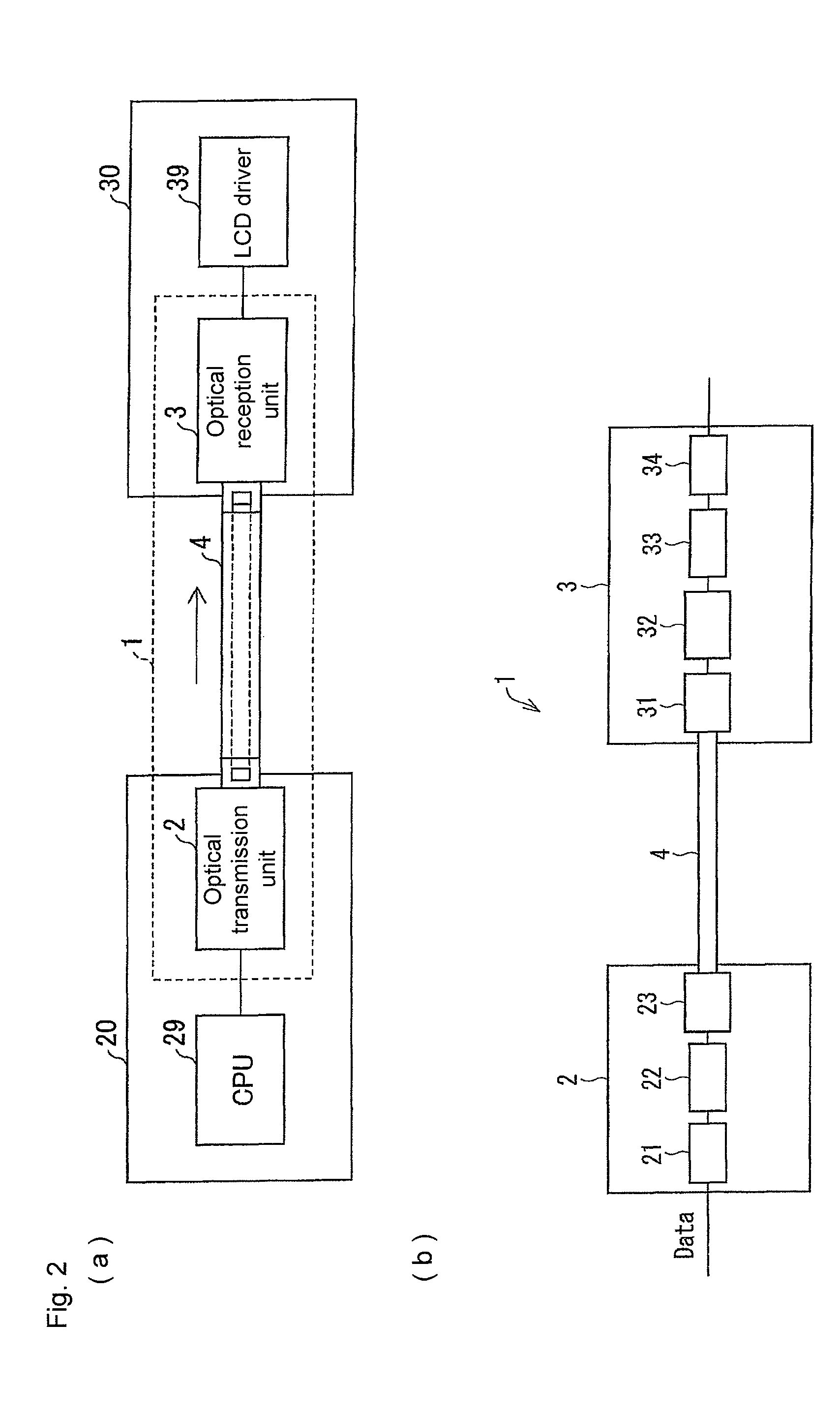
[0154]A modification of the configuration of the optical transmission module 1 according to one or more embodiments of the present invention illustrated in FIGS. 1(a) and 1(b) will be described below. FIG. 13 is a side view illustrating a configuration of an optical transmission module 1 according to Modification 1.

[0155]As illustrated in FIG. 13, in the optical transmission module 1 of Modification 1, a protective film 5 that protects the optical transmission path 4 is provided in one of a plurality of surfaces parallel to the optical transmission direction in the optical transmission path 4, as a member different from the member constituting the optical transmission path 4. The protective film 5 is a board film made of a material different from that of the member (optical transmission path 4) in which the optical signal is transmitted, and the fracture caused by the tension and wear-out of the optical transmission path 4 can be prevented by the protective film 5. In the plurality ...

modification 2

[0162]Another modification of the configuration of the optical transmission module 1 according to one or more embodiments of the present invention illustrated in FIGS. 1(a) and 1(b) will be described below. FIGS. 16(a) to 16(c) illustrate a configuration of an optical transmission module 1 according to Modification 2, wherein FIG. 16(a) is a top plan view, FIG. 16(b) is a side view, and FIG. 16(c) is an exploded perspective view. The optical transmission module 1 of Modification 2 is mounted while integrated with electric wiring (electric transmission path) 6.

[0163]As illustrated in FIGS. 16(a) to 16(c), the optical transmission module 1 of Modification 2 includes the electric wiring 6 in which the electric signal is transmitted between the transmission-side board 20 and the reception-side board 30. The optical transmission unit 2 and the optical reception unit 3 are mounted on the same surface in the electric wiring 6. The optical transmission path 4 is mounted on the optical trans...

modification 3

[0172]Still another modification of the configuration of the optical transmission module 1 according to one or more embodiments of the present invention illustrated in FIGS. 1(a) and 1(b) will be described below. FIG. 17 is a top plan view illustrating a configuration of an optical transmission module 1 according to Modification 3.

[0173]As illustrated in FIG. 17, the optical transmission module 1 of Modification 3 includes a guide unit 7 that guides the bending of the optical transmission path 4. The guide unit 7 is provided in one of the board surfaces of the transmission-side board 20 and the reception-side board 30. The guide unit 7 is disposed so as to extend in the direction vertical to the board surface. Therefore, the bending portion 4C of the optical transmission path 4 can be provided at the fixed position, and the bending of the optical transmission path 4 can stably be maintained.


PUM


Abstract

An optical transmission module has an optical transmission path in which optical transmission is performed between a first circuit board and a second circuit board disposed opposite the first circuit board. The optical transmission path has a folded structure having a bending radius. A circumferential portion drawn by the bending radius is provided substantially perpendicular to board surfaces of the first circuit board and the second circuit board.

Description

TECHNICAL FIELD[0001]The present invention relates to an optical transmission module, an electronic instrument, a method for assembling the optical transmission module, and an optical transmission method.BACKGROUND ART[0002]Recently, with a finer LCD (Liquid Crystal Display) of a mobile telephone, there is a demand for enhancement of a data transmission speed between the LCD and an application processor. In the data transmission wiring between circuit boards, there is also a demand for reduction of the number of wirings or a high bending property as a low profile of the mobile telephone progresses. Particularly, in a sliding type mobile telephone including a sliding mechanism that moves two circuit boards in parallel, it is necessary to generate wiring bending in a space (a distance between circuit boards is less than 3 mm) formed between the circuit boards. Therefore, in the sliding type mobile telephone, there is the noticeable demand for the high bending property of the wiring.[0...

Claims


Application Information

Patent Timeline
Patent Type & Authority Patents(United States)
IPC IPC(8): G02B6/12G02B6/00H04B10/25H04B10/2581H04B10/80H04M1/02
CPCG02B6/43H04B10/803G02B6/4214H05K1/0274H04M1/0235H05K1/14
Inventor HOSOKAWA, HAYAMIYASUDA, NARUHAMANA, KENTARO
Owner ORMON CORP
Why Eureka
Try Eureka