Method for producing a polycarbonate layered composite

a technology of polycarbonate and composites, applied in the direction of synthetic resin layered products, paper/cardboard containers, transportation and packaging, etc., can solve the problems of mechanical destruction of the chip, premature destruction or reduction of the life time of the components, and increase the mechanical pressure, so as to achieve substantial material savings and favorable effects

Active Publication Date: 2014-01-28
BUNDESDRUCKEREI GMBH
View PDF23 Cites 4 Cited by
  • Summary
  • Abstract
  • Description
  • Claims
  • Application Information

AI Technical Summary

Benefits of technology

[0013]Another advantage of the invention is that the liquid preparations used according to the invention, in particular solutions, can be applied by printing techniques and can therefore be employed for the conventional printing methods (e.g. screen, gravure, letterpress and flat printing, but also ink jet printing) with the respective (low) lateral layer thicknesses. This will lead, compared to adhesive films to be applied on the surface, to substantial savings of material. Commercially available adhesion systems (e.g. based on epoxides) can theoretically also be printed, would however change color during lamination or lose their adhesive properties.
[0014]The printing method also permits a position-resolved, non-full-surface application, and different layer thicknesses in a position-resolved manner.
[0015]In addition to printing, the liquid preparations also can be knife-coated, dispensed, sprayed, cast or spread.
[0016]In principle, arbitrary components can be used for the invention. The advantages according to the invention will however have a favorable effect in particular on components, which are mechanically and / or thermally sensitive, such as electronic components or (volume) holograms. Electronic components are for instance integrated circuits, thick-film circuits, circuits comprising several discrete active and passive components, sensors, chip modules, displays, batteries, coils, capacitors, contact points and many others.
[0017]The specific pressure (pressure at the workpiece) in step e) is typically in the range from 1 bar to 10 bars, in particular in the range from 3 bars to 7 bars. The temperature in step e) is preferably in the range from 140° C. to 180° C., in particular in the range from 150° C. to 170° C. The time of the step e) may be in the range from 0.5 s to 45 min, in particular from 10 to 30 min.
[0018]In step c), drying may be performed at a temperature in the range from 20° C. to 120° C., in particular from 60° C. to 120° C., preferably from 80° C. to 110° C., for a time of at least 1 min, preferably 5 min to 600 min, in particular from 10 min to 120 min.

Problems solved by technology

When integrating electronic components, in particular integrated semiconductors (IC's), but also chip modules, displays, batteries, coils, capacitors, contact points etc. in polycarbonate (PC) based documents, there is, for instance for thin semiconductor structures, a problem of premature destruction or reduced of life time of the components during the lamination by thermal and mechanical overload or stress.
Since PC does not immediately soften due to its specific heat transfer coefficient and its relatively high glass temperature Tg, there is an increased mechanical pressure directly at the chip, this pressure leading in most cases to a mechanical destruction of the chip.
Other environmental influences, in particular high temperatures, but also fast temperature changes may lead to that card splits open and cannot be used any longer.
Furthermore, adhesive films with a thickness <50 μm can only difficultly or not at all be handled on an industrial scale, and are inflexible, when it is important, e.g., to fill up cavities.
If the hologram is directly laminated with further PC films to form a card, this will happen under certain circumstances under visible and measurable losses of the representation quality of the hologram, in particular of the colors and the 3-dimensional appearance.
These effects, too, are based on the problem that either the “hard” PC is placed on brittle surfaces and causes mechanical stress or deforms softer bodies, for instance made from a photopolymer, thus these components being impaired in their function.

Method used


Image

  • Method for producing a polycarbonate layered composite
  • Method for producing a polycarbonate layered composite
  • Method for producing a polycarbonate layered composite

Examples


example 1

Making Polycarbonate Derivatives to be Used According to the Invention

example 1.1

Making a First Polycarbonate Derivative

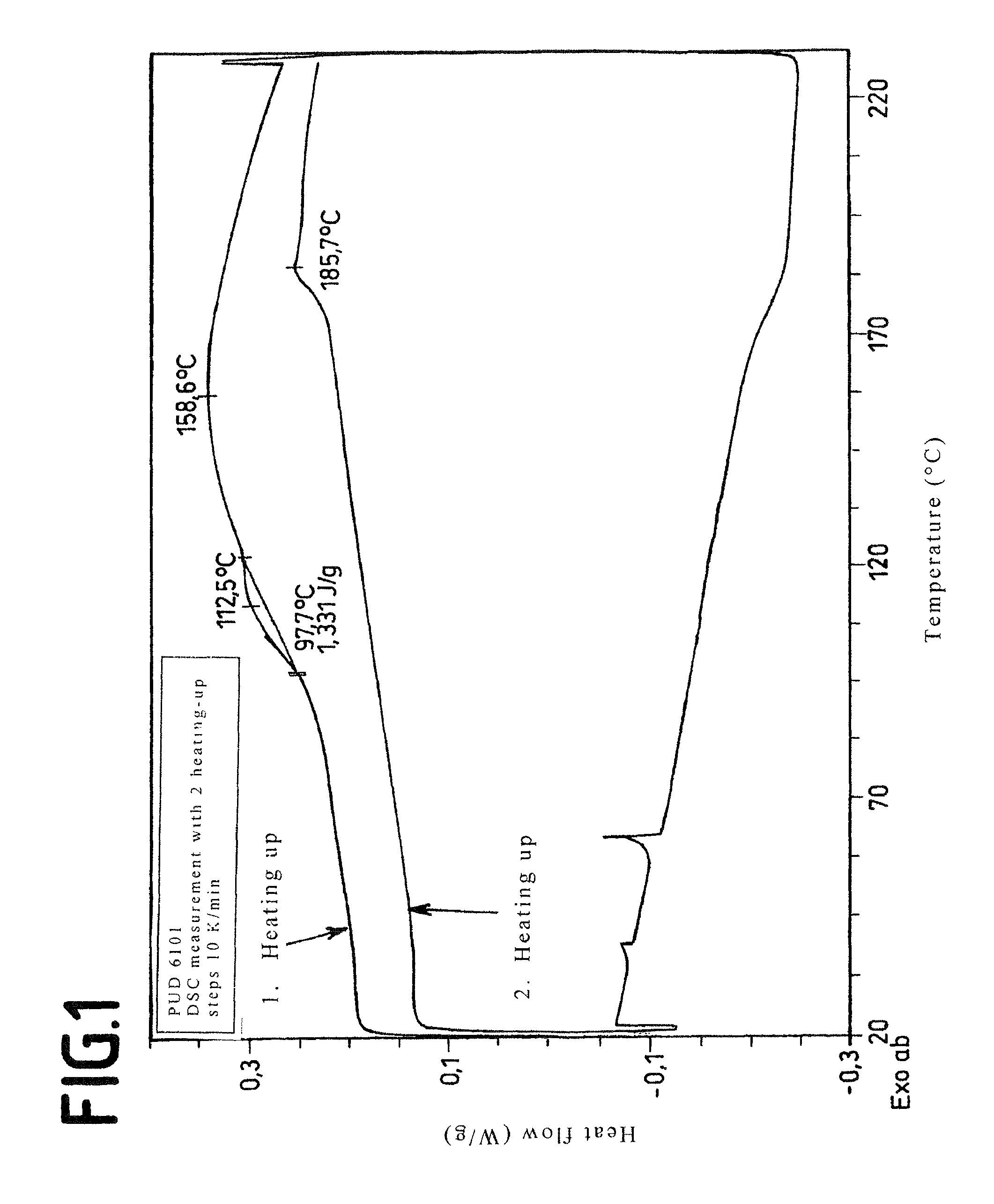
[0066]205.7 g (0.90 mole) bisphenol A (2,2-bis-(4-hydroxyphenyl)-propane, 30.7 g (0.10 mole) 1,1-bis-(4-hydroxyphenyl)-3,3,5-trimethyl cyclohexane, 336.6 g (6 mole) KOH and 2,700 g water are dissolved in an inert gas atmosphere under stirring. Then a solution of 1.88 g phenol in 2,500 ml methylene chloride is added. Into the well stirred solution, 198 g (2 mole) phosgene are introduced at pH 13 to 14 and 21 to 25° C. Then 1 ml ethylpiperidine is added and stirred for another 45 min. The bisphenolate-free aqueous phase is separated, after acidification with phosphoric acid, the organic phase is washed neutrally with water and freed from solvent.

[0067]The polycarbonate derivative had a relative solution viscosity of 1.255.

example 1.2

Making a Second Polycarbonate Derivative

[0068]In an analogous manner to Example 1.1, a mixture of 181.4 g (0.79 mole) bisphenol A and 63.7 g (0.21 mole) 1,1-bis-(4-hydroxyphenyl)-3,3,5-trimethyl cyclohexane was reacted to the polycarbonate.

[0069]The polycarbonate derivative has a relative solution viscosity of 1.263.


PUM

PropertyMeasurementUnit
temperatureaaaaaaaaaa
molar ratioaaaaaaaaaa
glass temperature Tgaaaaaaaaaa

Abstract

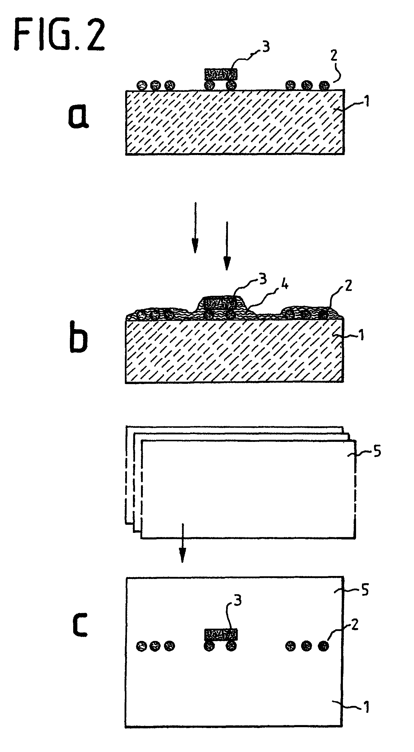
The invention relates to a method for making a structure with at least a first polymer layer and a second polymer layer, each made from a polycarbonate polymer based on bisphenol A, between the polymer layers a component being arranged, comprising the following steps: a) the component is arranged on the first polymer layer or placed in a depression of the first polymer layer, b) the first polymer layer is coated on the side, on which or in which the component is arranged, at least in the region of the component with a liquid preparation comprising a solvent or a mixture of solvents and a polycarbonate derivative based on a geminally disubstituted dihydroxydiphenyl cycloalkane, c) optionally a drying step is made after step b), d) after step b) or step c), the second polymer layer is placed on the first polymer layer, covering the component, e) the first polymer layer and the second polymer layer are laminated with each other under pressure, at a temperature from 120° C. to 180° C. and for a defined time.

Description

FIELD OF THE INVENTION[0001]The invention relates to a method for making a structure with at least a first polymer layer and a second polymer layer each made from a polycarbonate polymer based on bisphenol A, between the polymer layers a component being arranged, comprising the following steps: the component is arranged on the first polymer layer or placed in a depression of the first polymer layer, then the second polymer layer is placed on the first polymer layer, covering the component, and the first polymer layer and the second polymer layer are laminated with each other under pressure, at an increased temperature and for a defined time. The invention further relates to a structure obtainable in this way, to the use of the method for making a security and / or value document, and to a security and / or value document to be thus made.BACKGROUND OF THE INVENTION AND PRIOR ART[0002]When integrating electronic components, in particular integrated semiconductors (IC's), but also chip mod...

Claims


Application Information

Patent Timeline
Patent Type & Authority Patents(United States)
IPC IPC(8): B32B3/08B32B37/14
CPCB42D2033/30B42D25/455B42D2031/22B32B37/142B42D15/0013B42D15/10B32B2425/00B32B2305/342B42D25/46B42D2031/24B32B2369/00B42D25/00B42D25/29Y10T428/195Y10T156/10Y10T428/239Y10T428/23B32B27/365B42D25/21B42D25/23B42D25/24B42D25/328
Inventor MUTH, OLIVERLEOPOLD, ANDREPFLUGHHOEFFT, MALTEFISCHER, JORGPAESCHKE, MANFREDPUDLEINER, HEINZYESILDAG, CENGIZMEYER, KLAUS
Owner BUNDESDRUCKEREI GMBH
Why Eureka
Try Eureka