Integrated gasification combined cycle system with vapor absorption chilling

a gasification combined cycle and vapor absorption chilling technology, applied in the direction of combustible gas production, sustainable manufacturing/processing, lighting and heating apparatus, etc., can solve the problems of high cost of cooling tower water for carbon dioxide compressors, large auxiliary compression power, and low overall power plant net output and efficiency

Active Publication Date: 2014-01-21
AIR PROD & CHEM INC
View PDF17 Cites 3 Cited by
  • Summary
  • Abstract
  • Description
  • Claims
  • Application Information

AI Technical Summary

Problems solved by technology

The compression of carbon dioxide, however, generally requires large amounts of auxiliary compression power.
This type of parasitic load thus results in lower overall power plant net output and efficiency.
Moreover, the use of cooling tower water to cool the carbon dioxide compressors may be expensive and impractical in areas where water may be expensive and / or rare.

Method used


Image

  • Integrated gasification combined cycle system with vapor absorption chilling
  • Integrated gasification combined cycle system with vapor absorption chilling
  • Integrated gasification combined cycle system with vapor absorption chilling

Examples


Embodiment Construction

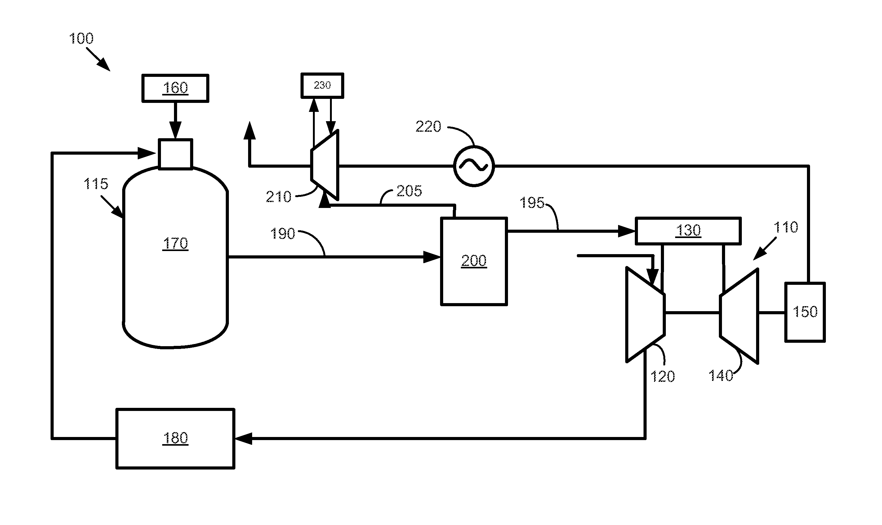
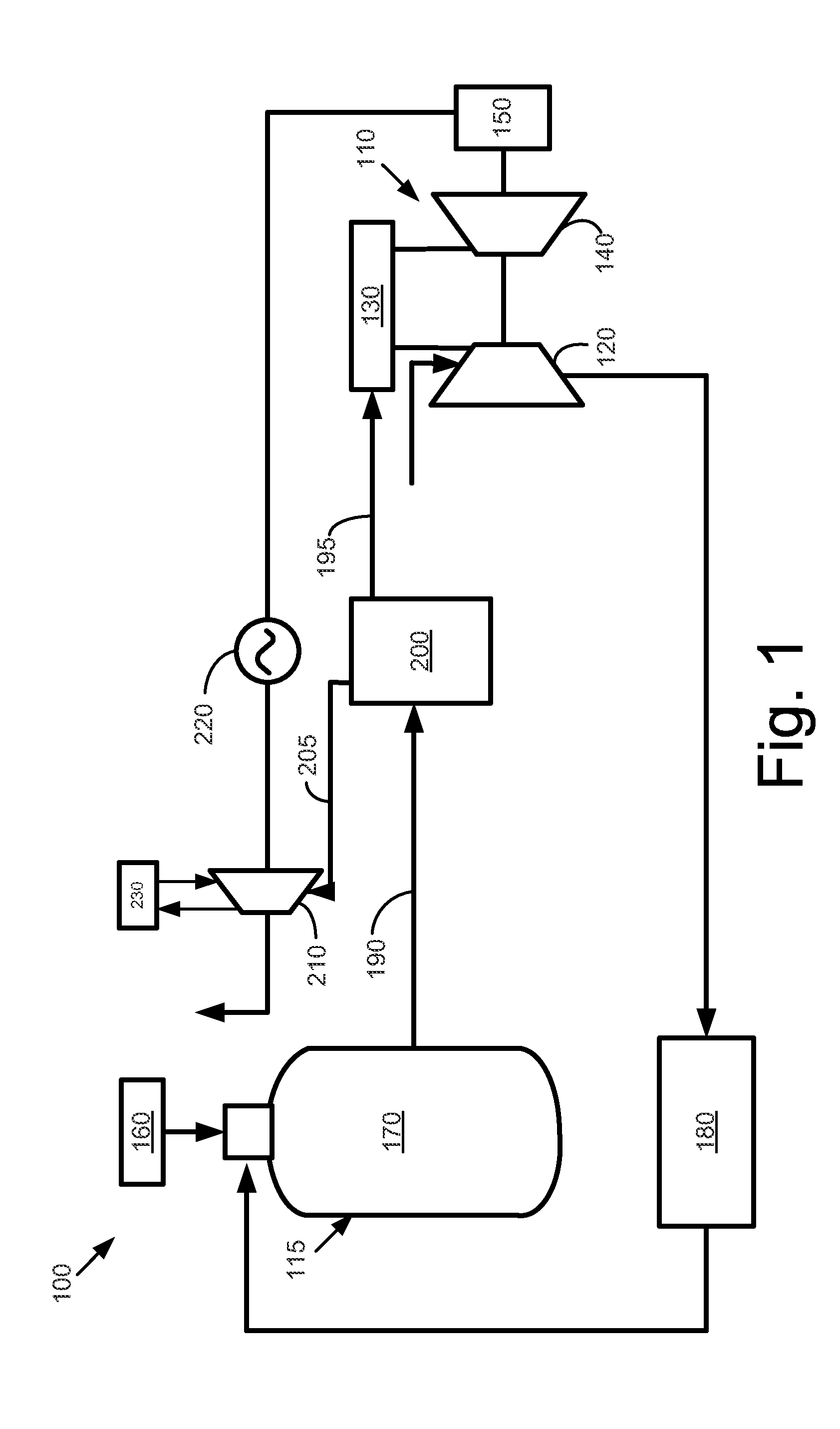
[0013]Referring now to the drawings, in which like numerals refer to like elements throughout the several views, FIG. 1 shows a schematic view of a known integrated gasification combined cycle system 100. Only those elements related to the subject matter described herein are shown for purposes of simplification. The overall integrated gasification combined cycle system 100 may have many other configurations and may use many other types of equipment.

[0014]The integrated gasification combined cycle system 100 may include one or more gas turbine engines 110. As is known, the gas turbine engine 110 may include a compressor 120 to compress an incoming flow of air. The compressor 120 delivers the compressed flow of air to a combustor 130. The combustor 130 mixes the compressed flow of air with a compressed flow of fuel and ignites the mixture. Although only a single combustor 130 is shown, the gas turbine engine 110 may include any number of combustors 130. The hot combustion gases are in...


PUM


Abstract

The present application and the resultant patent provide an integrated gasification combined cycle system. The integrated gasification combined cycle system may include a gas turbine engine, one or more power plant components, one or more carbon dioxide compressors, and a vapor absorption chiller. The vapor absorption chiller is driven by a waste heat source flow from the carbon dioxide compressors to produce a chilling medium flow to cool the power plant components.

Description

TECHNICAL FIELD[0001]The present application relates generally to integrated gasification combined cycle systems and more particularly relates to an integrated gasification combined cycle system using vapor absorption chilling driven by the waste heat of a gas compression system.BACKGROUND OF THE INVENTION[0002]Generally described, carbon dioxide (“CO2”) produced in power generation facilities is considered to be a greenhouse gas. As such, the carbon dioxide produced in the overall power production process generally is sequestered and then recycled for other purposes or otherwise disposed. In current integrated gasification combined cycle (“IGCC”) systems, the pre-combustion capture of carbon dioxide is preferred. Once captured, the carbon dioxide generally may be compressed before transport, disposal, or other use. Specifically, various integrated gasification combined cycle system designs require the compression of the carbon dioxide before the gas is recycled to, for example, the...

Claims


Application Information

Patent Timeline
Patent Type & Authority Patents(United States)
IPC IPC(8): F25B7/00
CPCF25B15/02C10J3/466F25B27/02Y02E20/16F02C7/143F01K23/068Y02E20/185C10J2300/1678F02C3/28C10J3/00Y02E20/18C10J2300/1653Y02B30/625F25B15/00F01K23/067Y02E20/32Y02P20/10Y02P20/129Y02P80/15Y02A30/274
Inventor PEMMI, BHASKARSHARMA, ANIL KUMARSAHA, RAJARSHIMAZUMDER, INDRAJITZHOU, QIONGROBBINS, CHRISTOPHER MICHAELSCARBORO, PAUL ROBERTSDRISCOLL, ANN VERWILST
Owner AIR PROD & CHEM INC
Why Eureka
Try Eureka