Eureka AIR delivers breakthrough ideas for toughest innovation challenges, trusted by R&D personnel around the world.

Cartridge assembly having an integrated retention system

a technology of retaining system and cartridge, which is applied in the direction of cartridge ammunition, weapons, shotgun ammunition, etc., can solve the problems of premature igniting of propellant charges, significant shortened reloading times in gun systems, and significant safety risks, and achieves high tensile strength strap, high strength, and high tensile strength

Inactive Publication Date: 2014-01-14
BAE SYSTEMS LAND & ARMAMENTS LP
View PDF16 Cites 0 Cited by
  • Summary
  • Abstract
  • Description
  • Claims
  • Application Information

AI Technical Summary

Benefits of technology

[0009]The advent of automated reloading systems has significantly shortened reloading times in gun systems. However, the rapid reloading capabilities provided by automated reloading systems have also created significant safety risks. An automated reloading system allows a single gun system to fire multiple projectiles in rapid succession, often before the firing chamber has an opportunity to cool from the previously fired rounds. As propellant charges are combustibles that can ignite when exposed to high temperatures, the propellant charges can prematurely ignite if the cartridge cap is displaced, exposing the propellant charges inside the cartridge case to high temperatures or if the propellant charges escape the cartridge case and come into contact with the hot interior walls of the firing chamber.
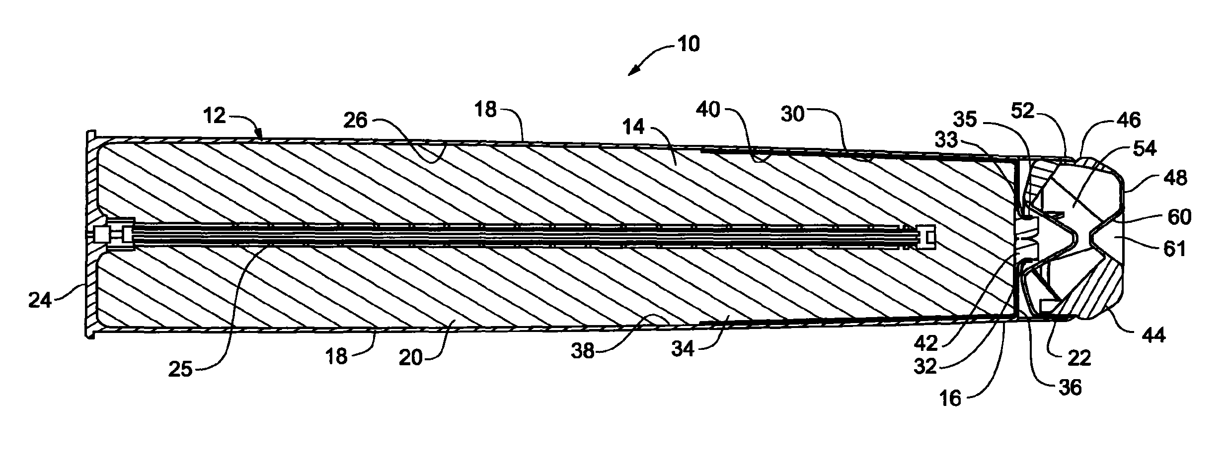
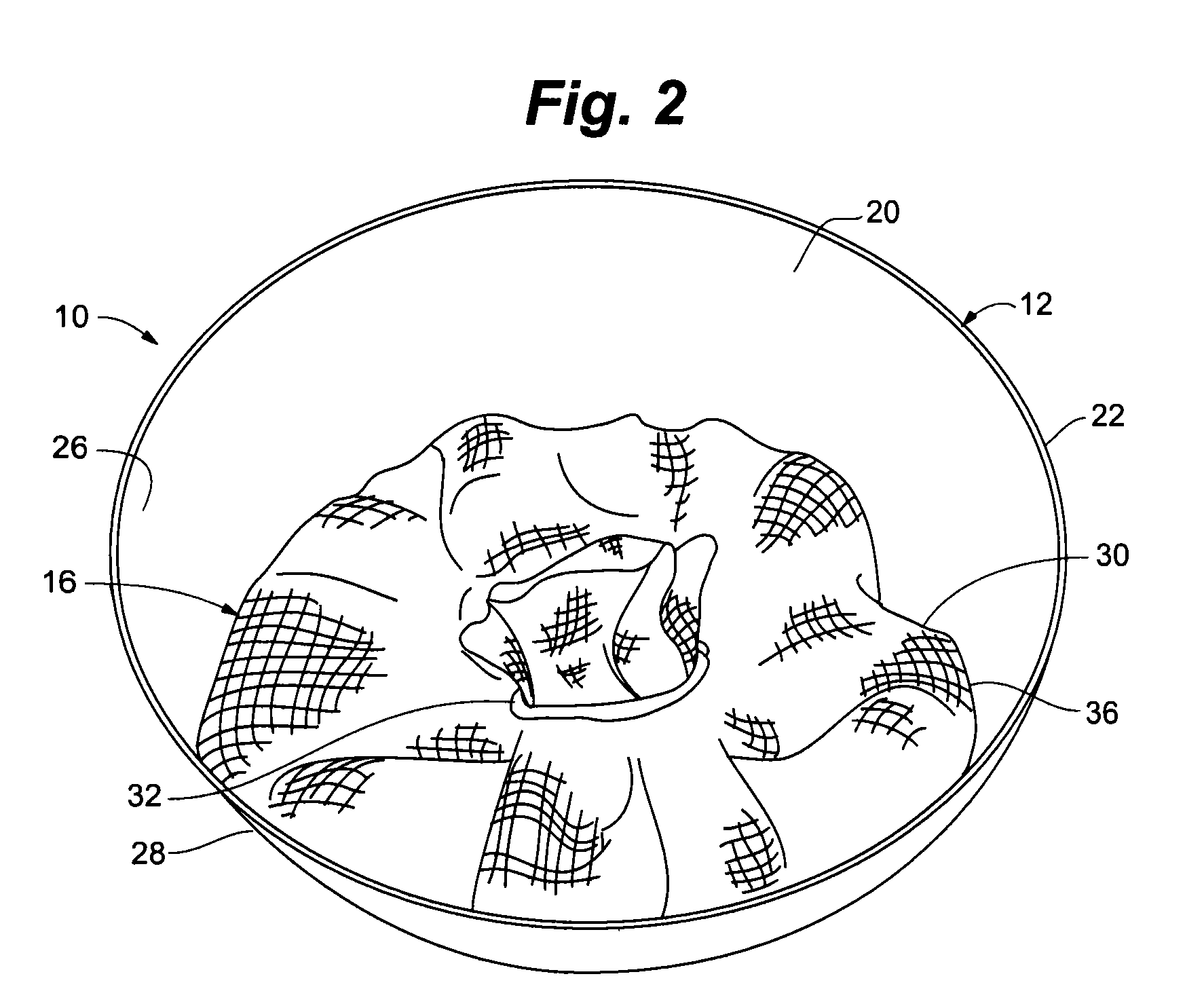
[0012]In an example embodiment, the insulating sleeve is formed from a high tensile strength, insulating material that secures the propellant charge and inhibits the propellant charge from moving toward the proximate end of the cartridge case during loading of a cartridge or extraction of a misfired cartridge case. The insulating sleeve also insulates the propellant charges from hot gases and surfaces within the firing chamber when the cartridge case is loaded into a hot firing chamber.
[0013]According to an embodiment of the invention, a high tensile strength strap can be used to secure and crimp the insulating sleeve closed at its proximate end. In another aspect of the invention, an adhesive strip can be affixed to the insulating sleeve to reinforce the high tensile strength strap to assist in securing the insulating sleeve against opening during loading of the cartridge or extraction of a misfired cartridge. High strength and temperature resistant adhesive or adhesive tape is used to affix the insulating sleeve to the cartridge case and help keep the insulating sleeve closed.
[0014]According to an embodiment of the invention, a closure plug can be inserted into the proximate end of the cartridge case to assist in efficient use of the gases generated by the ignited propellant charges. According to an embodiment of the invention, the closure plug can include a distal conical indent or other space defined for receiving the crimped portion of the interior bag so that the closure plug evenly sits in the proximate end of the cartridge case. The closure plug can also have a proximate conical indent or other shaped indentation for interfacing with certain irregularly shaped projectiles.

Problems solved by technology

The advent of automated reloading systems has significantly shortened reloading times in gun systems.
However, the rapid reloading capabilities provided by automated reloading systems have also created significant safety risks.
As propellant charges are combustibles that can ignite when exposed to high temperatures, the propellant charges can prematurely ignite if the cartridge cap is displaced, exposing the propellant charges inside the cartridge case to high temperatures or if the propellant charges escape the cartridge case and come into contact with the hot interior walls of the firing chamber.
In a misfire the propellant charge does not properly ignite.
Removing misfired or unfired propellant charges from the firing chamber can also create a risk of unintended ignition, if the propellant charges spill from the cartridge case as the misfired cartridge case is extracted from the firing chamber and contact hot surfaces within the firing chamber if the gun has been previously fired.

Method used


Image

  • Cartridge assembly having an integrated retention system
  • Cartridge assembly having an integrated retention system
  • Cartridge assembly having an integrated retention system

Examples


Embodiment Construction

[0048]Cartridge assembly 10 including a closure plug 44 as depicted in FIG. 7 was tested utilizing an inert propellant charge 14. Inert propellant charge 14 had a mass of 28.5 kilograms and was positioned with 1.5 inches of clearance between closure plug 44 and propellant charge 14. Insulating sleeve 30 was formed of wool / rayon, bonded to cartridge case 12, interior surface 26 with 3M-1099 adhesive. 1.5 inches of foam wadding 88 was placed between propellant charge 14 and closure plug 44 and cartridge assembly 10 was rammed at 10.0 meters per second. Under these circumstances, movement of closure plug 44 was limited to 0.142 inches. In another test, closure plug 44 moved 0.077 inches after 2 ram tests. Closure plug 44 remained intact and inert propellant charge 14 was retained.

[0049]In another test, an inert propellant charge 14 having a mass of 28.5 kilograms was positioned with 0.5 inches clearance between it and closure plug 44 as depicted in FIG. 7. Insulating sleeve 30 was form...


PUM


Abstract

A cartridge assembly for large bore gun systems having an integrated retention assembly for maintaining propellant charges within the cartridge case. The cartridge case having an interior space for receiving propellant charges and an open proximate end through which the propellant charges can be fed. An insulating sleeve defining an interior channel is affixed to the cartridge case and extends out of the proximate end of the cartridge case. The interior channel serves as a chute through which propellant charges can be fed. After the propellant charges are loaded, the insulating sleeve is crimped closed to retain the propellant charges within the cartridge case. A closure plug can be inserted into the proximate end of the cartridge case after the insulating sleeve is crimped closed.

Description

RELATED APPLICATIONS[0001]This application claims the benefit of U.S. Provisional Patent Application 61 / 353,914 filed Jun. 11, 2010 entitled “Cartridge Assembly Having an Integrated Retention System.” the entire contents of which are hereby incorporated by reference.GOVERNMENT LICENSE RIGHTS[0002]This invention was made with Government support under U.S. Government Contract N00024-05-C-5117, awarded by The Naval Sea Systems Command. The government has certain rights in the invention.FIELD OF THE INVENTION[0003]The present invention is generally directed to an apparatus and related methods for retaining propellant charges within cartridge cases during loading and firing of gun systems. More specifically, the present invention is directed to a cartridge assembly having an integrated retention system for retaining propellant charges within cartridge cases for use in gun systems having automated loading systems.BACKGROUND[0004]Large land based artillery and naval gun systems often emplo...

Claims


Application Information

Patent Timeline
Patent Type & Authority Patents(United States)
IPC IPC(8): F42B33/02F42B5/26
CPCF42B5/285
Inventor SEVERSON, GREGG, J.
Owner BAE SYSTEMS LAND & ARMAMENTS LP
Why Eureka
Eureka Blog
Learn More