Eureka AIR delivers breakthrough ideas for toughest innovation challenges, trusted by R&D personnel around the world.

Rapid loading system for rocket launcher

A rocket launcher and loading technology, which is applied in the direction of weapon accessories, ammunition supply, offensive equipment, etc., can solve the problems of affecting flexibility, long loading time, and increasing the load of the whole vehicle, so as to achieve strong safety and reliability, shorten loading time, and improve The effect of loading efficiency

Inactive Publication Date: 2022-04-12
JIANGSU EFFICIENCY ROBOTICS SYST CO LTD
View PDF0 Cites 0 Cited by
  • Summary
  • Abstract
  • Description
  • Claims
  • Application Information

AI Technical Summary

Problems solved by technology

[0004] 1. Manually load the bombs directly into the launch tube, but this loading method is not only inefficient, but also has high strength and slow loading speed; the rockets are loaded one by one into the launch tube with the help of a sling, which requires a special sling The tool is on the carrier, which increases the load of the vehicle and affects its flexibility
[0005] 2. The rocket launcher must be fired before the rockets can be loaded one by one, which takes a long time to load and is inefficient
[0006] 3. The loading action is completed by hydraulic components such as oil cylinders and hydraulic pumps. Its action accuracy is not high, and it is easy to shift after a long push distance, which affects the straightness of delivery, and is prone to a series of dangerous situations such as jamming. Safety , Poor stability
[0007] 4. When the rocket launcher is used in a harsh environment, hydraulic transmission components such as oil cylinders and hydraulic pumps are easily blocked by wind and sand, or frozen by ice and snow, which affects its transmission accuracy and stability, and easily affects the use of the rocket launcher

Method used


Image

  • Rapid loading system for rocket launcher
  • Rapid loading system for rocket launcher
  • Rapid loading system for rocket launcher

Examples


Embodiment Construction

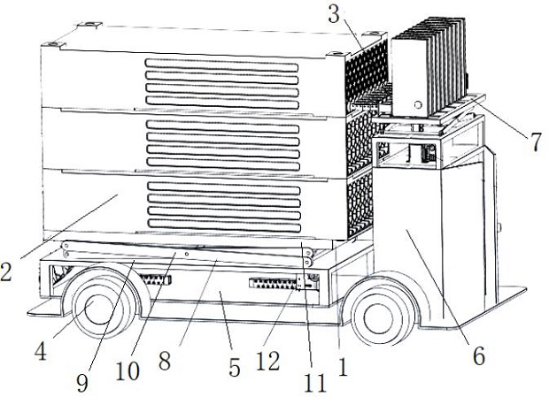
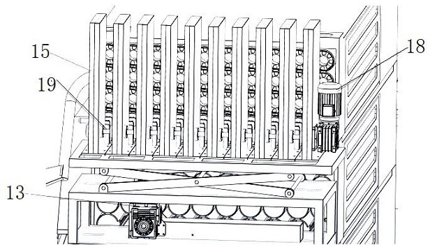
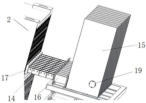
[0032] see Figure 1 to Figure 3 , The present invention relates to a rocket launcher rapid loading system, which is mainly composed of a loading vehicle 1, a loading box 2 and a pushing mechanism 3.

[0033] The loading vehicle 1 is located at the rear side of the rocket carrier vehicle. The bottom of the loading vehicle 1 is provided with wheels 4, which move the loading vehicle 1 through the wheels 4, and the wheels 4 are equipped with locking mechanisms. When the loading vehicle 1 is positioned The trolley can be locked with a locking mechanism to prevent it from moving. The front end of the top of the loading trolley 1 is a platform 5, on which a filling box lifting mechanism 8 is fixed, and the top and rear end of the filling trolley 1 is provided with a box body 6. Various control electrical appliances are placed inside the box body 6 to control the transmission system. The top of the box body 6 is a holding platform 7, and the pushing mechanism 3 is placed on the top o...


PUM


Abstract

The invention relates to a quick loading system for rocket launchers, which consists of a loading vehicle, a loading box and a pushing mechanism, a platform is arranged at the front end of the top of the loading vehicle, and a loading box lifting mechanism is fixed on the platform; a box body is arranged at the rear end of the top of the filling vehicle, a containing table is arranged at the top of the box body, a shear fork mechanism is arranged at the bottom of the containing table, and the pushing mechanism is fixed to the top of the containing table and composed of a row of pushing rigid chains arranged side by side. Compared with an original manual loading and lifting appliance loading mode, the loading box prepared in advance can be used for pushing a row of rocket projectiles into a launcher at a time through the rigid chain pushing mechanism at the speed of 300 mm / s, loading of a row of rocket projectiles with the length of 6 m can be completed only in 20 seconds, and the loading efficiency is greatly improved. Five rows of rocket projectiles in the whole loading box can be loaded within two minutes, so that the loading speed is high, the loading time is greatly shortened, and real-time loading can be efficiently completed on a field battlefield.

Description

technical field [0001] The invention relates to a rapid loading system for a rocket launcher, which is a multi-engine joint launching device. Background technique [0002] The rocket launcher is composed of a launcher, a rotary mechanism, an aiming device, a power supply, a launch ignition control device, and a carrier vehicle. Among them, the launcher of the rocket launcher is a multi-shot joint launching device for launching rockets. The rockets launched by it rely on the thrust of its own engine to fly. Fire a large number of rockets in a short period of time. [0003] The main composition of the rocket launcher is a multi-tube modular launch box. There are multiple rows of launch tubes arranged side by side in the launch box. The launch tubes are filled with rockets to be launched. When all the rockets in the launch tubes are launched After that, it is necessary to carry out the loading work. The previous loading method was mainly manual loading or spreader loading, b...

Claims


Application Information

Patent Timeline
Patent Type & Authority Applications(China)
IPC IPC(8): F41A9/38
Inventor 居才平
Owner JIANGSU EFFICIENCY ROBOTICS SYST CO LTD
Why Eureka
Eureka Blog
Learn More