Power line filter

a power line and filter technology, applied in the direction of reducing harmonics/ripples, dc circuits, coupling device connections, etc., can solve the problems of short distance between them, easy cracking, and easy detachment of insulating tape wrapping the outside of the ground inductor, and achieves high yield.

Active Publication Date: 2014-01-07
DELTA ELECTRONICS INC
View PDF6 Cites 16 Cited by
  • Summary
  • Abstract
  • Description
  • Claims
  • Application Information

AI Technical Summary

Benefits of technology

[0006]The present invention is to provide a power line filter, especially a size-reduced, material-saving, labor-saving and high-yield power line filter.

Problems solved by technology

However, because the filter inductor and the ground inductor are both disposed in the receptacle of the housing, the distance between them is quite short.
Thus, the filter inductor, the ground inductor or other inductor elements are vulnerable to be interfered by each other so as to influence the filtering results.
Additionally, the insulating tape wrapping the outside of the ground inductor is easily detached and cracked, and its insulating efficacy is quite limited as well.
It results in generating sparks due to a high voltage difference, which is occasionally induced between the filter inductor and the ground inductor by a significant variation of magnetic fields at the moment of being powered on or off.
This severely endangers the safety of use.

Method used


Image

  • Power line filter
  • Power line filter
  • Power line filter

Examples


Embodiment Construction

[0016]The present invention will be apparent from the following detailed description, which proceeds with reference to the accompanying drawings, wherein the same references relate to the same elements.

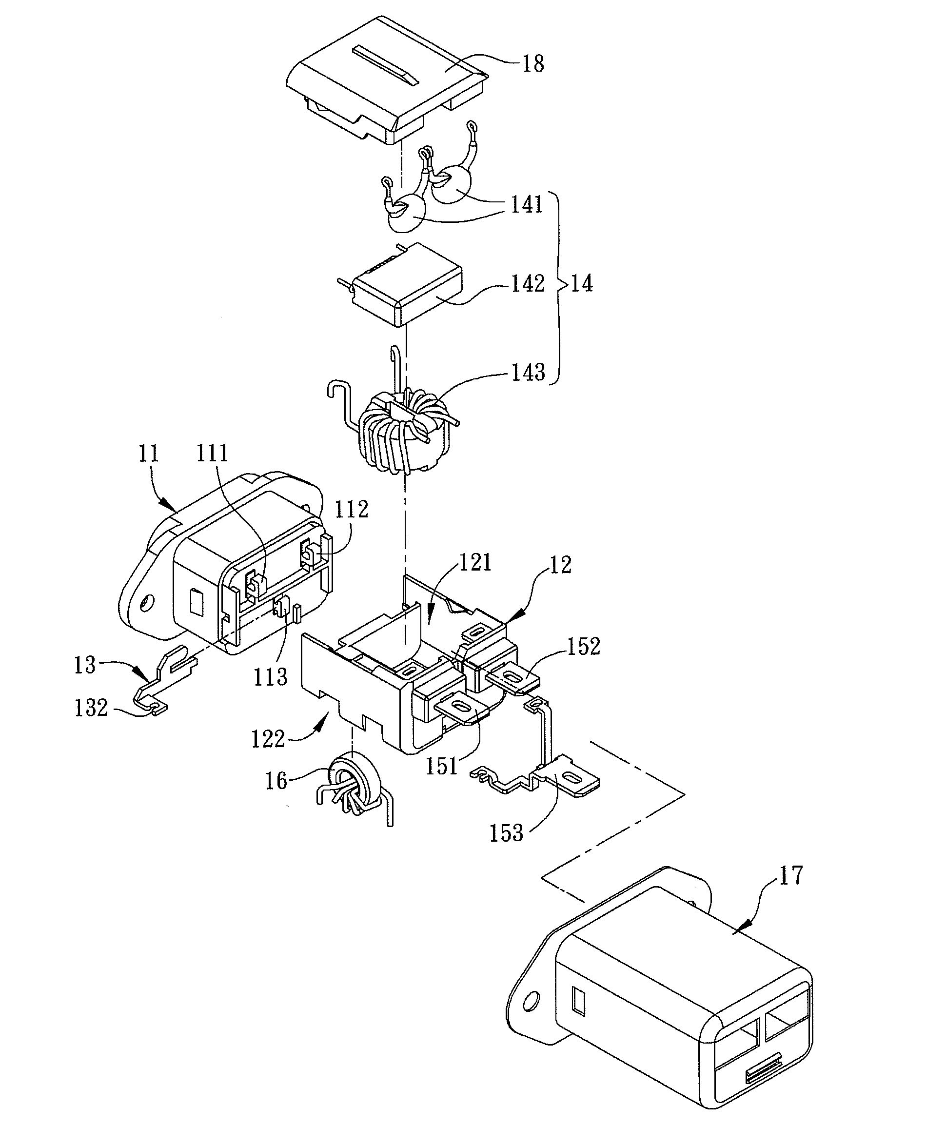
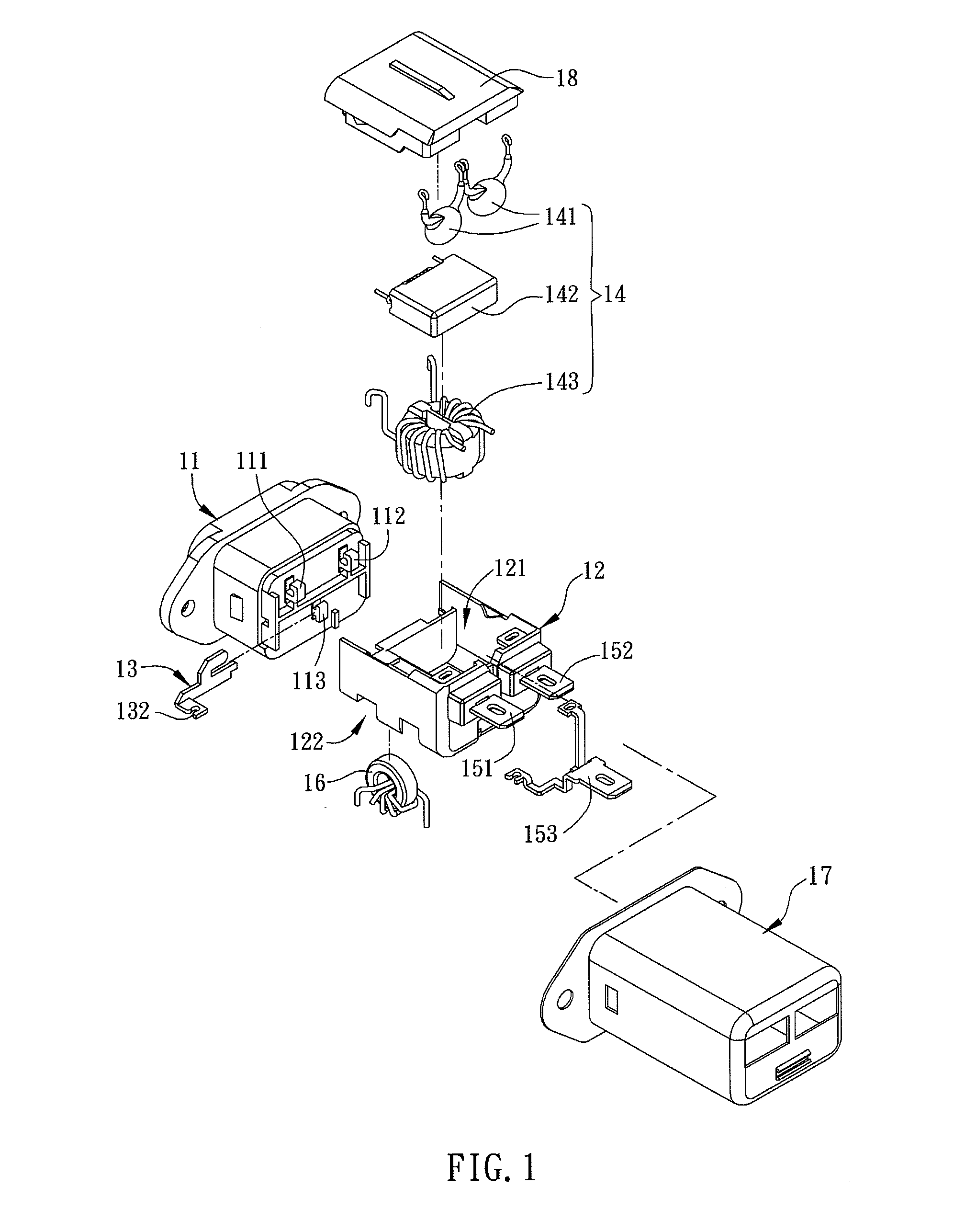
[0017]As shown in FIG. 1, a power line filter in accordance with a preferred embodiment of the present invention includes a socket 11, a housing 12, a plurality of filter elements 14 and a ground inductor 16. The socket 11 includes a first power pin 111, a second power pin 112 and a ground pin 113. The housing 12 is assembled with the socket 11, and has a first receptacle 121 and a second receptacle 122. The opening direction of the first receptacle 121 is opposite to the opening direction of the second receptacle 122. In more detailed, the opening of the first receptacle 121 is upward, but the opening of the second receptacle 122 is downward. The plurality of filter elements 14 is disposed in the first receptacle 121, and at least one of the filter elements 14 is electrically connect...


PUM


Abstract

A power line filter including a socket, a housing, a plurality of filter elements and a ground inductor is disclosed. The socket includes at least one power pin and a ground pin. The housing is assembled with the socket, and includes a first receptacle and a second receptacle. The opening direction of the first receptacle is opposite to the opening direction of the second receptacle. The plurality of filter elements is disposed in the first receptacle. At least one of the filter elements is electrically connected to the power pin. The ground inductor is disposed in the second receptacle and electrically connected to the ground pin.

Description

CROSS REFERENCE TO RELATED APPLICATIONS[0001]This Non-provisional application claims priority under 35 U.S.C. §119(a) on Patent Application No. 098133794 filed in Taiwan, Republic of China on Oct. 6, 2009 the entire contents of which are hereby incorporated by reference.BACKGROUND OF THE INVENTION[0002]1. Field of Invention[0003]The present invention relates to a power line filter, and, in particular, to a size-reduced, material-saving, labor-saving and high-yield power line filter.[0004]2. Related Art[0005]The basic structure of a conventional power line filter is composed of a socket and a housing disposed at one side of the socket. The electronic elements such as an X capacitor, a Y capacitor, a filter inductor and a ground inductor are disposed in the receptacle of the housing. However, because the filter inductor and the ground inductor are both disposed in the receptacle of the housing, the distance between them is quite short. Furthermore, the ground inductor is generally wra...

Claims


Application Information

Patent Timeline
Patent Type & Authority Patents(United States)
IPC IPC(8): H01R13/66H02J3/01H03H7/01
CPCH01R13/6625H01R2103/00H01R13/6633H01R13/6616H01R13/6608H01R24/78
Inventor HSIEH, SHIN-CHIHTSAI, PO-JEN
Owner DELTA ELECTRONICS INC
Why Eureka
Try Eureka