
Ratchet clip

a ratchet and clip technology, applied in the field of ratchet clips, can solve the problems of affecting the color and quality of the paper the reading material is printed on, and the current device is not readily adjustable to user preferences or reading conditions, etc., and achieves the effect of reducing the amount of light required, and improving the quality of the reading material

Inactive Publication Date: 2014-01-07
SIGHT SAVER
View PDF47 Cites 3 Cited by
  • Summary
  • Abstract
  • Description
  • Claims
  • Application Information

AI Technical Summary

Benefits of technology

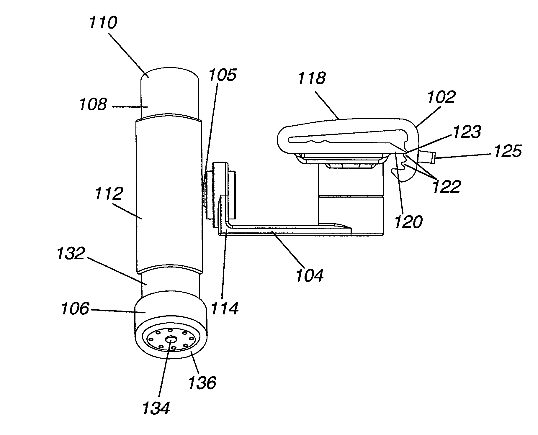
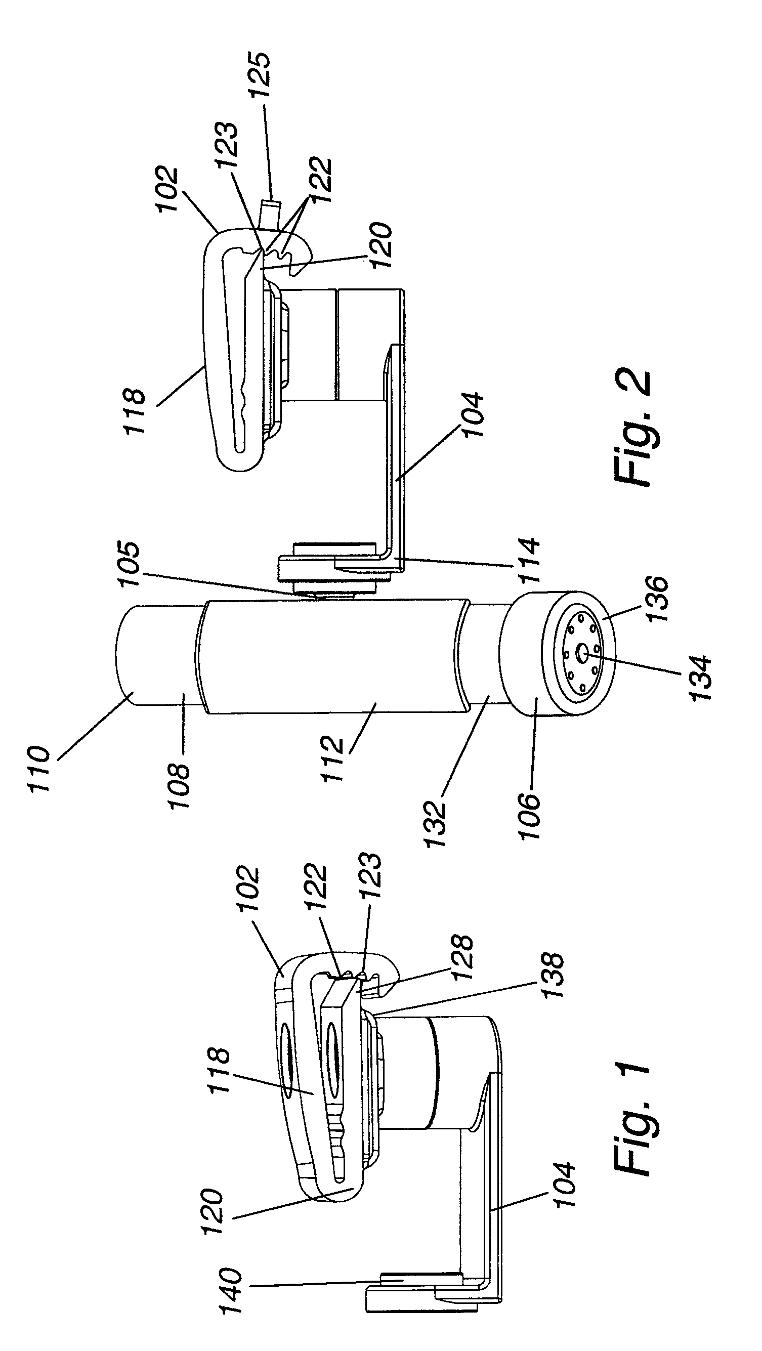
The patent is about a mounting system for an illumination system that can be attached to thin or small structures, like eyewear. The system has two parts: an adapter clip and an offset arm. The adapter clip connects to the structure, while the offset arm has a snap mechanism that allows for rotation. This mechanism allows for adjustment and directed lighting in different directions. The technical effect of this invention is that it provides a way to easily attach a light to eyewear and adjust its position for optimal visibility.

Problems solved by technology

Therefore, the current devices are not readily adjustable to either user preferences or reading conditions.
In addition, the integral and / or fixed nature of the prior art devices make repairs, such as battery replacement of the lighting device, difficult or impossible.
The type, color, and quality of the paper the reading material is printed on also affects the amount of light required.
The inability to adjust to these and other variables may result in increasing the potential for eye strain or eye fatigue rather than minimizing it.
One disadvantage to this type of construction is that the power source(s), wiring, switches, etc., must also be built into the frames.
Many of the changes required to incorporate the hardware make the designs unpopular for fashion and add significant weight to the assembly.
For example, many jobs require workers to perform their duties in poorly lit work environments in an area where it is impractical to bring in an external light source.
For example, the light extends away from the helmet making it susceptible to being caught in wiring, tree limbs, structures and the like.
Because the light bracket is rigidly attached to the hard hat, this may create a dangerous situation.
In addition, the rigid attachment and thumbscrews prevent quick removal of the light for hand held usage.
Still yet, the rigidly fixed mount does not provide the angular adjustment necessary for some lighting requirements.
Large lights, such as ceiling lights, often result in shadows being cast on areas of interest since the person is often positioned between the area of interest and the light source.
Also, some such lights are designed to light large areas and cannot be directed without affecting illumination in some areas meant to be illuminated.
These lights tend to be large and require adjustment if the user moves and needs to redirect the light; requiring use of one or more hands to effect the light redirection, hands that may be busy doing other jobs.
Such lights, while being somewhat effective, have limits, particularly in the ability to redirect over a large range of adjustment, and sometimes being fixed in place or requiring hands to redirect.

Method used


Image

  • Ratchet clip
  • Ratchet clip
  • Ratchet clip

Examples


Embodiment Construction

[0057]While the present invention is susceptible of embodiment in various forms, there is shown in the drawings and will hereinafter be described a presently preferred, albeit not limiting, embodiment with the understanding that the present disclosure is to be considered an exemplification of the present invention and is not intended to limit the invention to the specific embodiments illustrated.

[0058]FIGS. 1-35, which are now referenced, illustrate illuminations systems 100, 200, 300 and 400, which are different embodiments of the present invention. A first embodiment 100, illustrated in FIGS. 1-6, is constructed and arranged for securement to eyewear. A second embodiment 200, illustrated in FIGS. 7-11, is constructed and arranged for securement to a hard hat. A third embodiment 300, illustrated in FIGS. 12 and 13, is constructed and arranged for securement to a hard hat. A fourth embodiment 400, illustrated in FIGS. 7-11, is constructed and arranged for securement to a hard hat. E...


PUM


Abstract

This invention relates generally to an illumination system that is configured for attachment to a hard hat or the temple arm portion of a pair of eyeglasses. The illumination system includes a light source and a multi-axis pivot assembly to permit directional adjustment and focus of a beam of light. An adapter clip is provided to facilitate attachment to the temple arm portion of the eyeglasses. The adapter clip includes a plurality of grooves positioned between two flexible side portions to allow the clip to be slid along the temple arm to a desired position and snapped into a locked position. The illumination system is fully adjustable in terms of light intensity and direction of the light beams.

Description

REFERENCE TO RELATED APPLICATIONS[0001]In accordance with 37 C.F.R 1.76, a claim of priority is included in an Application Data Sheet filed concurrently herewith. Accordingly, the present invention claims the benefit of the filing date and / or priority under 35 U.S.C. 119(e), 120, 121, and / or 365(c) to U.S. Provisional Patent Application No. 61 / 555,332, filed Nov. 3, 2011, entitled, “Ratchet Clip”. This application is also related to following applications: U.S. patent application Ser. No. 13 / 166,401, filed Jun. 22, 2011, entitled “Attachable Illumination System”; which claims priority of U.S. Provisional Patent Application No. 61 / 357,791, filed Jun. 23, 2010; entitled, “Attachable Illumination System”; U.S. patent application Ser. No. 12 / 878,713, filed Sep. 9, 2010, entitled “Light System”; which claims priority of U.S. Provisional Patent Application No. 61 / 242,839, filed Sep. 16, 2009, entitled, “Light System”, and U.S. Provisional Patent Application No. 61 / 357,791, filed Jun. 23, ...

Claims


Application Information

Patent Timeline
Patent Type & Authority Patents(United States)
IPC IPC(8): F21V21/00F21V17/06
CPCA42B3/044F21V21/28A42B3/04F21V21/145F21V21/084
Inventor CRISTOFORO, MICHAEL
Owner SIGHT SAVER
Learn More