
Smoking article

a technology of smoking article and smoke, which is applied in the field of smoking article, can solve the problems of reducing ignition performance, reducing the diameter of the heat source, and the heat source is enclosed in the heat-insulating jacket, so as to reduce the number of components, increase the diameter, and increase the ignition performance

Active Publication Date: 2013-12-31
JAPAN TOBACCO INC
View PDF11 Cites 44 Cited by
  • Summary
  • Abstract
  • Description
  • Claims
  • Application Information

AI Technical Summary

Benefits of technology

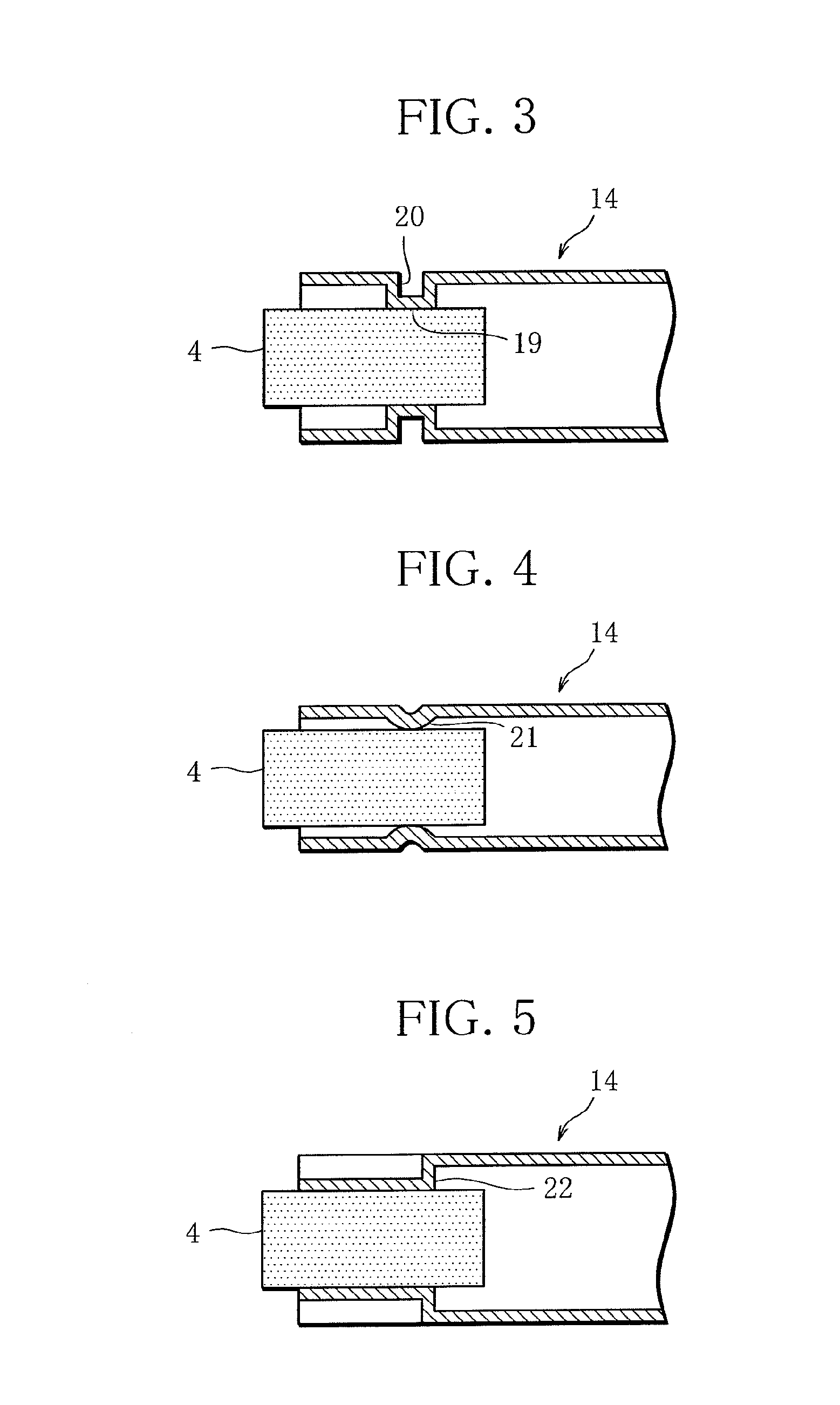
The present invention provides a tube member with a carbon heat source held in the holder part, which increases the ignition performance of the heat source. The carbon heat source is held without the need for a separate holding member, reducing the number of components, assembly steps, and costs. The holder part with a plurality of projections or a turned edge can reliably hold the carbon heat source. The carbon heat source may have a circumferential groove for increased reliability of holding, and a pin can also be inserted to improve reliability. These features make the holding process more efficient and cost-effective.

Problems solved by technology

This way of holding the heat source is costly because of use of the heat-insulating jacket formed from a glass mat or the like.
There is also concern that the carbon heat source enclosed in the heat-insulating jacket may exhibit problems such as decreased ignition performance.
The smoking article disclosed in patent document 2 is however complicated in structure.

Method used


Image

  • Smoking article
  • Smoking article
  • Smoking article

Examples


Embodiment Construction

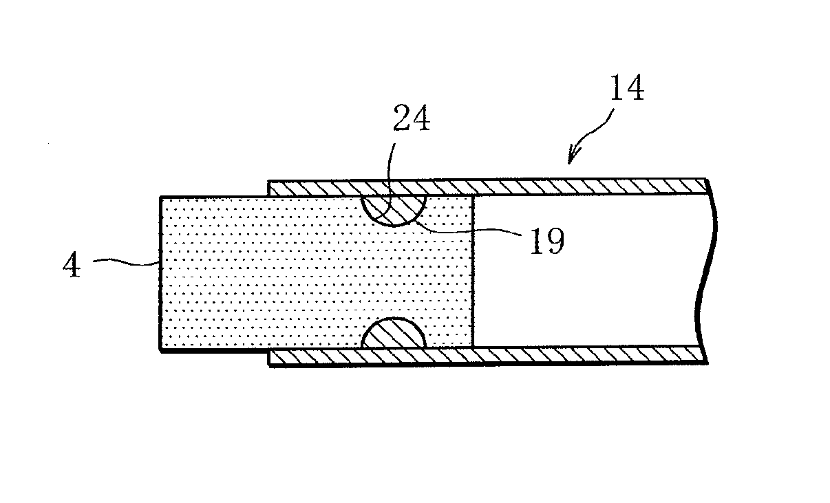
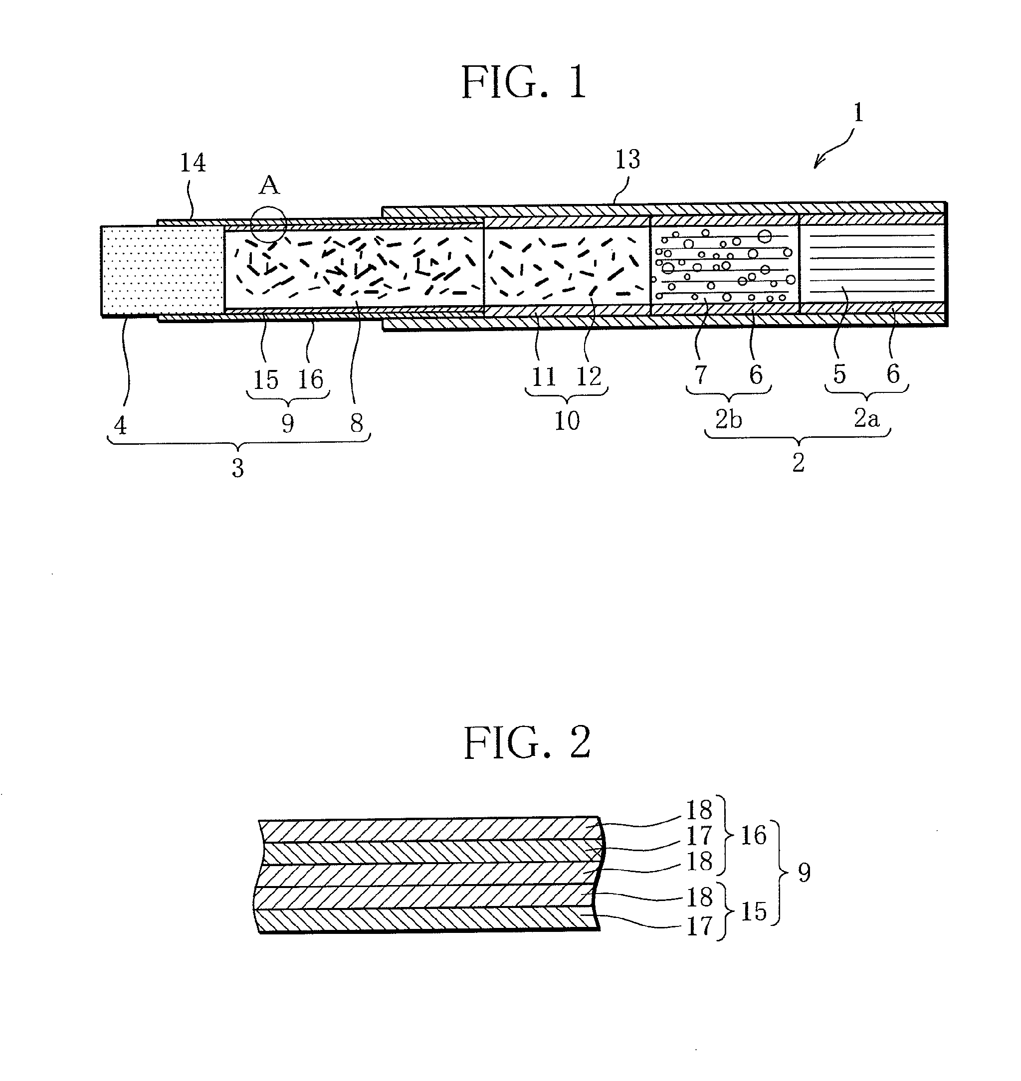
[0037]As seen in FIG. 1, a smoking article 1 according to the present invention comprises a tobacco rod 3. The tobacco rod 3 comprises a carbon heat source 4, a smoking flavor releasing source 8 and a non-combustible wrapper (tube member) 9. The tobacco rod 3 is aligned with a filter 2. The filter 2 is located at a mouth end. In the illustrated example, the filter 2 is a double filter composed of a plain filter segment 2a and a charcoal filter segment 2b. The filter 2 is however not restricted to this type. The plain filter segment 2a is formed by wrapping filter fiber 5 in rolling paper 6. The charcoal filter segment 2a is formed by wrapping activated carbon-containing filter fiber 7 in rolling paper 6. Although omitted in the illustration, the filter 2 is further wrapped in forming paper. The tobacco rod 3 is formed by wrapping a tobacco shreds-containing smoking flavor releasing source 8 in a non-combustible wrapping material 9. Specifically, the non-combustible wrapping material...


PUM


Abstract

A smoking article comprises a multilayered tube member (9) including at least one metal layer and one paper layer, a carbon heat source (4) arranged in an end portion of the tube member (9) to be at least partly in direct close contact with an inner surface of the tube member (9), the carbon heat source emitting heat when ignited, a smoking flavor releasing source (8) arranged in the tube member (9) to adjoin the carbon heat source (4), and a holder part (14) keeping the carbon heat source (4) in direct contact with said end portion and holding the carbon heat source (4) against said end portion.

Description

CROSS REFERENCE TO RELATED APPLICATION[0001]This application is a continuation of PCT / JP2010 / 055365 filed on Mar. 26, 2010,which is hereby expressly incorporated by reference into the present application.[0002]This invention relates to a smoking article having a carbon heat source.BACKGROUND ART[0003]Smoking articles with a carbon heat source arranged at an end to transfer heat to a smoking flavor releasing source are known (see patent document 1, for example). In the smoking article disclosed in patent document 1, the carbon heat source is enclosed in a heat-insulating jacket formed from a glass mat or the like and held at an end of the smoking article by elasticity of the heat-insulating jacket. This way of holding the heat source is costly because of use of the heat-insulating jacket formed from a glass mat or the like. It also takes a step of wrapping the heat source in a glass mat. There is also concern that the carbon heat source enclosed in the heat-insulating jacket may exhi...

Claims


Application Information

Patent Timeline
Patent Type & Authority Patents(United States)
IPC IPC(8): A24F1/32A24D1/22A24D3/17
CPCA61M15/06A24B15/165A24F47/006A61M2011/047A61M11/047A24D3/17A24D1/22
Inventor TSURIZUMI, RYUTAROSASAKI, HIROSHIHAMAMOTO, NAOKIWATANABE, TOMOICHI
Owner JAPAN TOBACCO INC
Learn More