Eureka AIR delivers breakthrough ideas for toughest innovation challenges, trusted by R&D personnel around the world.

DC-DC converter

a converter and dc technology, applied in the direction of electric variable regulation, process and machine control, instruments, etc., can solve problems such as efficiency reduction, and achieve the effect of reducing not only the turn-off loss but also the turn-on loss

Active Publication Date: 2013-12-24
MITSUBISHI ELECTRIC CORP
View PDF14 Cites 6 Cited by
  • Summary
  • Abstract
  • Description
  • Claims
  • Application Information

AI Technical Summary

Benefits of technology

[0007]It is an object of the present invention to provide a DC-DC converter capable of reducing not only the turn-off loss but also the turn-on loss.
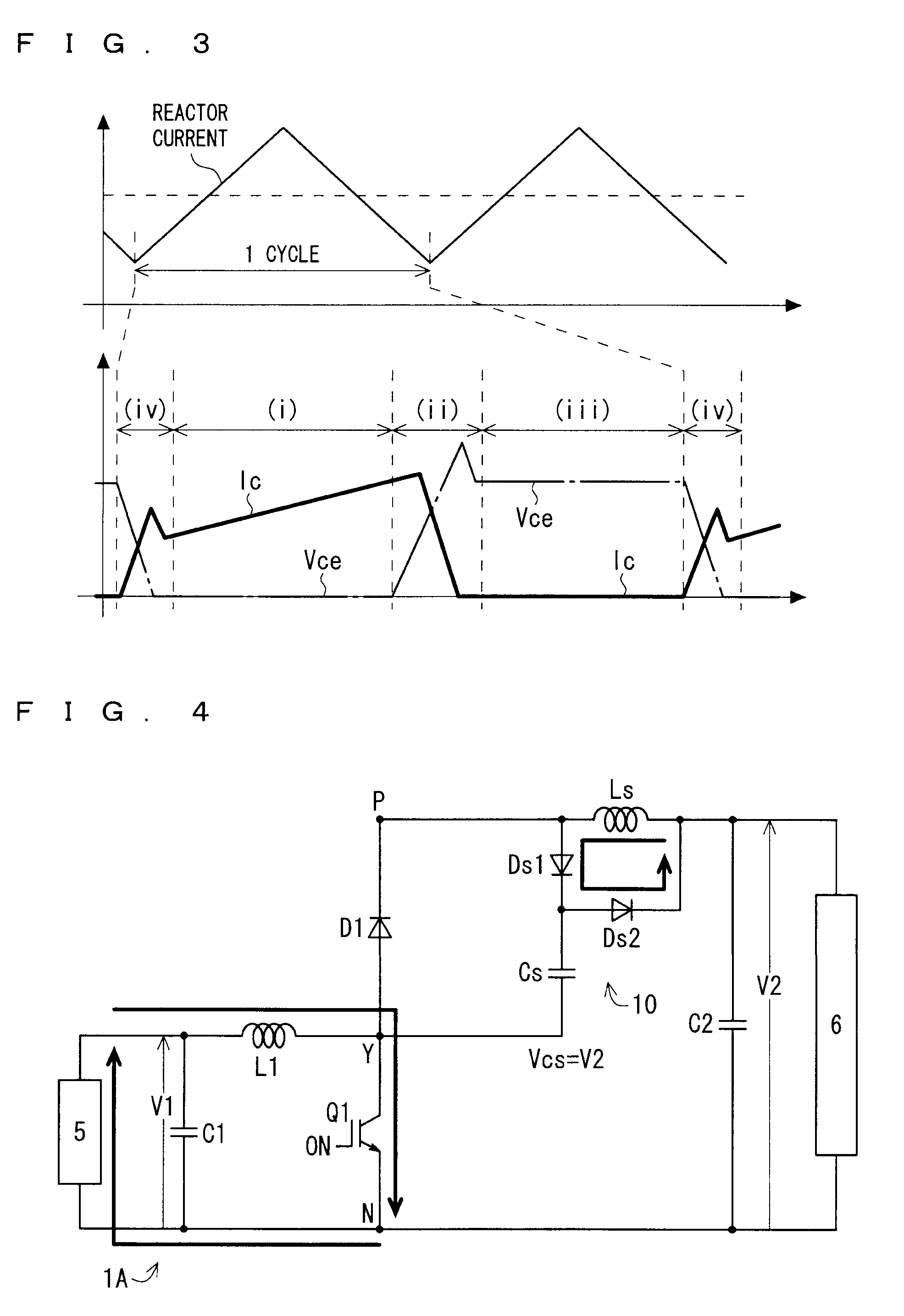
[0009]In accordance with the aspect described above, not only the turn-off loss but also the turn-on loss can be reduced in the step-up operation. Moreover, the switching loss is reduced, whereby the efficiency enhancement and downsizing of the device can be achieved even if the switching frequency is increased. Moreover, an occurrence of electromagnetic noise can be suppressed by the soft switching. Furthermore, a snubber circuit is composed of a small number of parts, and accordingly, it is possible to suppress significant upsizing and cost increase, and further, reduction of the efficiency, which may be caused by the upsizing. Moreover, the snubber circuit does not require complicated control for itself, and accordingly, can easily realize the soft switching.

Problems solved by technology

Furthermore, a snubber circuit is composed of a small number of parts, and accordingly, it is possible to suppress significant upsizing and cost increase, and further, reduction of the efficiency, which may be caused by the upsizing.

Method used


Image

  • DC-DC converter
  • DC-DC converter
  • DC-DC converter

Examples


first preferred embodiment

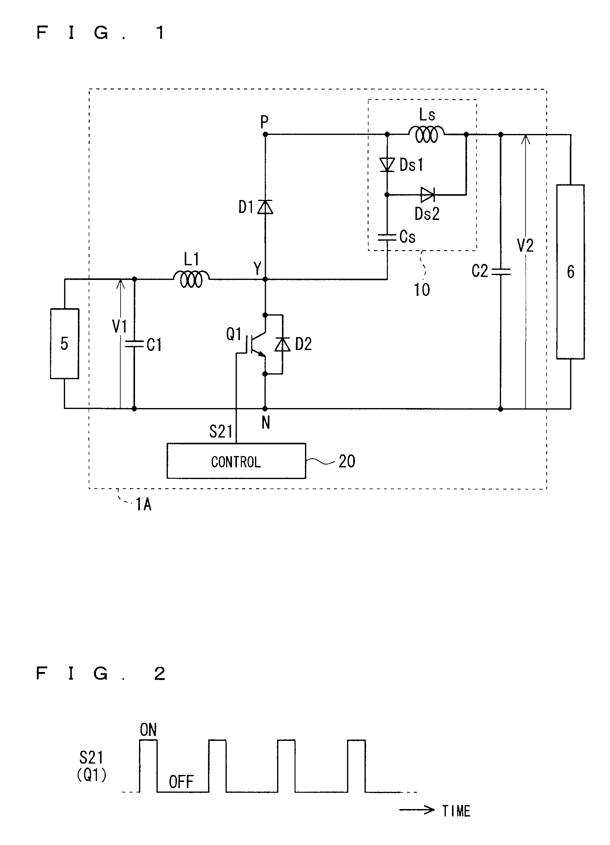
[0033]FIG. 1 shows a circuit diagram schematically showing a configuration of a DC-DC converter (hereinafter, sometimes abbreviated as a converter) 1A according to a first preferred embodiment. As illustrated in FIG. 1, the converter 1A is used by being connected between a low voltage-side device 5 and a high voltage-side device 6. In other words, the low voltage-side device 5 is connected to low voltage-side connection ends of the converter 1A, and the high voltage-side device 6 is connected to high voltage-side connection ends of the converter 1A.

[0034]The converter 1A is a step-up converter, and has a configuration capable of executing a step-up operation in which a voltage V1 on the low voltage-side connection ends is stepped up to a voltage V2 (>V1) and the stepped-up voltage V2 is outputted to the high voltage-side connection ends. In other words, the converter 1A steps up the voltage V1, which is applied thereto by the low voltage-side device 5, to the voltage V2, and supplie...

second preferred embodiment

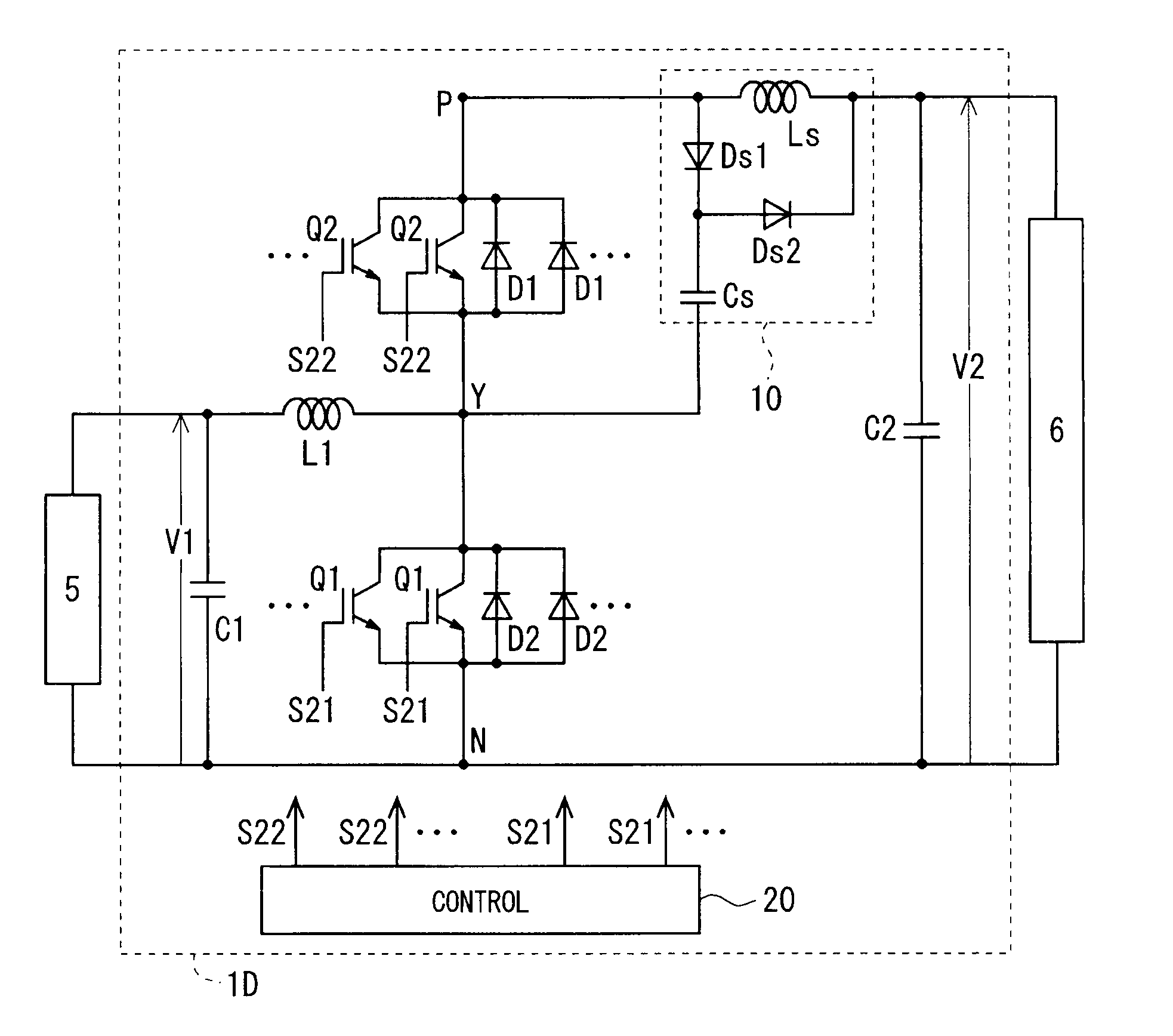
[0087]FIG. 13 shows a circuit diagram schematically showing a configuration of a converter 1B according to a second preferred embodiment. The converter 1B is a so-called bidirectional step-up / down (also referred to as bidirectional) converter. That is, the converter 1B has a configuration capable of executing both of the step-up operation (the voltage V1 on the low voltage-side connection ends is stepped up to the voltage V2, and the stepped-up voltage V2 is outputted to the high voltage-side connection ends) and a step-down operation (the voltage V2 on the high voltage-side connection ends is stepped down to the voltage V1, and the stepped-down voltage V1 is outputted to the low voltage-side connection ends). In other words, in the step-up operation, the converter 1B steps up the voltage V1, which is applied by the low voltage-side device 5, to the voltage V2, and supplies the stepped-up voltage V2 to the high voltage-side device 6. On the other hand, in the step-down operation, th...

third preferred embodiment

[0122]FIG. 24 shows a circuit diagram schematically showing a configuration of a converter 1C according to a third preferred embodiment. The converter 1C illustrated in FIG. 24 has a configuration in which the step-up transistor Q1 is removed from the bidirectional step-up / down converter 1B (see FIG. 13) according to the second preferred embodiment. That is, the converter 1C is tailored to be step-down. Other configurations of the converter 1C are basically similar to those of the converter 1B. Note that, from a viewpoint of the step-down operation, it is also possible to omit the step-up diode D1.

[0123]Note that, in the third preferred embodiment, the case is illustrated, where the low voltage-side device 5 is a variety of loads or a rechargeable battery, and the high voltage-side device 6 is a DC power supply (which may be a device in which an AC generator and an inverter are combined with each other, and the like).

[0124]In accordance with the converter 1C, in the step-down operat...


PUM


Abstract

Provided is a DC-DC converter capable of reducing not only a turn-off loss but also a turn-on loss. A snubber capacitor has one end connected to an anode of a step-up diode, a current input end of a step-up switching element and a main reactor. A first snubber diode has a cathode connected to other end of the snubber capacitor, and an anode connected to a cathode of the step-up diode. A second snubber diode has an anode connected to the cathode of the first snubber diode and other end of the snubber capacitor. A snubber reactor has one end connected to the anode of the first snubber diode, and other end connected to a cathode of the second snubber diode.

Description

BACKGROUND OF THE INVENTION[0001]1. Field of the Invention[0002]The present invention relates to a DC-DC converter.[0003]2. Description of the Background Art[0004]In a power step-up DC-DC converter that handles a high voltage and a large current, a switching frequency by a chopper circuit is increased, whereby efficiency enhancement and downsizing of a device can be achieved. However, the increase of the frequency results in an increase of a switching loss of a power semiconductor element that performs switching. Accordingly, from a viewpoint of the switching loss, the increase of the frequency becomes a cause to inhibit the efficiency enhancement and downsizing of the device. Note that such a problem is not limited to the power step-up converter.[0005]In order to reduce the switching loss, a soft switching circuit is sometimes used. In Japanese Patent Application Laid-Open No. 2004-201369, there is described a soft switching circuit for reducing a switching loss at the time when a ...

Claims


Application Information

Patent Timeline
Patent Type & Authority Patents(United States)
IPC IPC(8): G05F1/24
CPCH01L25/072H01L25/16H02M3/155H02M1/34H02M2001/346Y02B70/1491H01L2224/32225H01L2224/48137H01L2224/48227H01L2224/73265H01L2924/3011H01L2924/30107H01L2924/3025H01L2924/13055H01L2224/48091H01L2924/1305H01L2924/00H01L2924/00014Y02B70/10H02M1/346H02M3/1584
Inventor HATAE, SHINJIHUSSEIN, KHALID HASSAN
Owner MITSUBISHI ELECTRIC CORP
Why Eureka
Eureka Blog
Learn More