
Engineered residual stress in golf clubs

a residual stress and golf club technology, applied in the field of golf clubs, can solve the problems of no discussion of the process used for the striking surface of the ball, no commercial application of the process, and act too much like, so as to improve the effect of reducing the characteristic time characteristic of the golf club, and enhancing the performance of the golf club

Inactive Publication Date: 2013-12-17
METAL IMPROVEMENT CO INC
View PDF11 Cites 41 Cited by
  • Summary
  • Abstract
  • Description
  • Claims
  • Application Information

AI Technical Summary

Benefits of technology

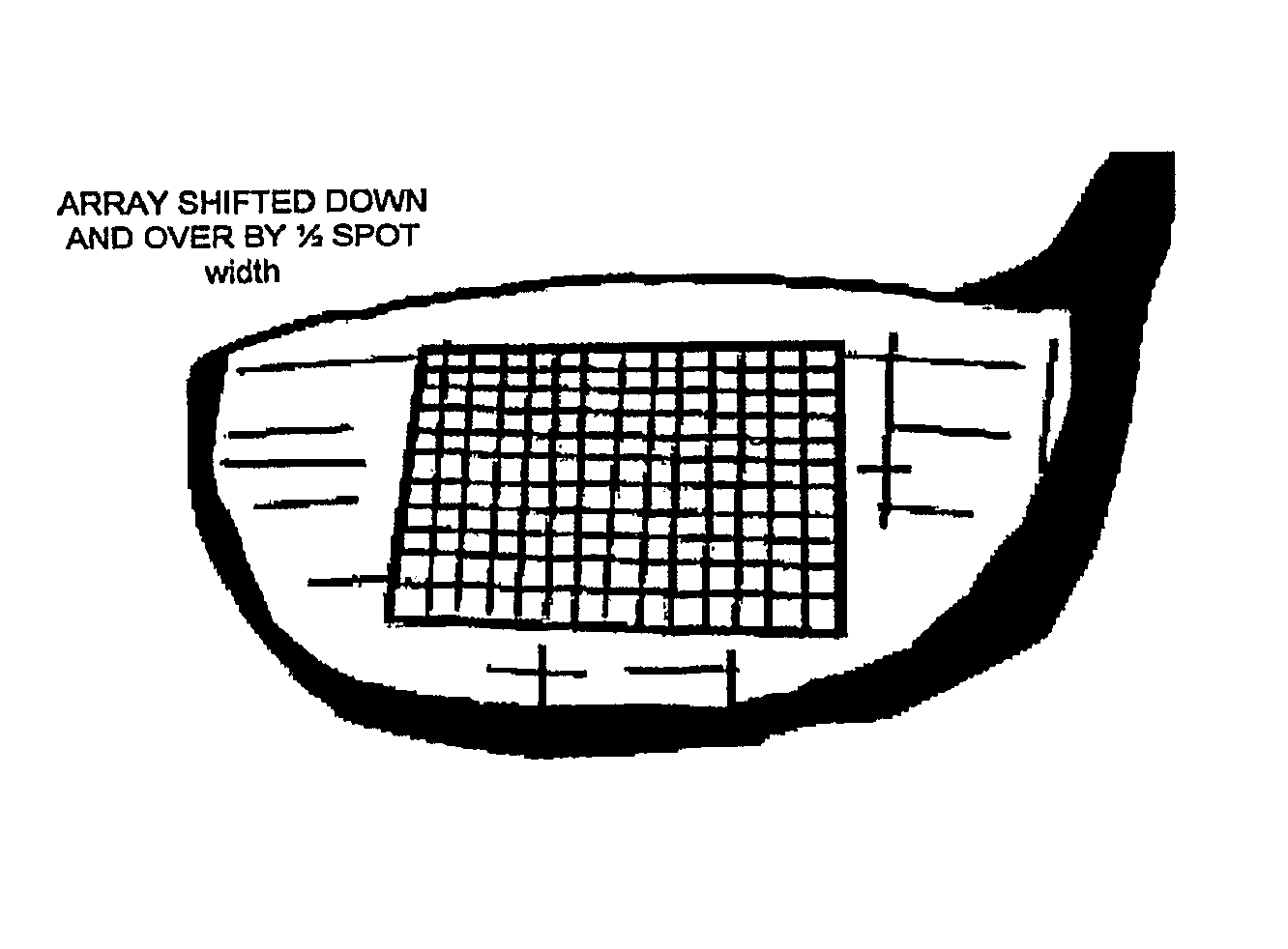
This patent describes a process of improving the performance of golf club faces by using high intensity laser shock peening. The process involves creating a pattern on the club face by laser shock peening the interior area while leaving the perimeter unpeened. This creates a stress gradient between the interior area and the perimeter, which reduces the time it takes for the club to complete a swing. Multiple layers of laser shock impact zones can also be used to create greater depth and magnitude of compressive stress, leading to even improved clubhead performance. The technology can be applied to assembled club heads without damaging their surfaces, and can be applied to both the outside and inside surfaces of the club face for even better durability.

Problems solved by technology

However, no discussion of the process used for the ball striking surface is provided.
If the COR is too high, the club is deemed to act too much like a spring, and is ruled illegal.
Although shot peening has been investigated for the purposes of treating golf clubs to harden the surface, reduce the coefficient of friction, induce residual compressive stress and remove [alpha]-case for at least 12 years, no commercial application of the process is known to the present inventor suggesting that the prior art process has failed to provide significant improvement in golf club manufacturing.

Method used


Image

  • Engineered residual stress in golf clubs
  • Engineered residual stress in golf clubs
  • Engineered residual stress in golf clubs

Examples


Embodiment Construction

[0039]A detailed description of embodiments of the present invention is provided with reference to the FIGS. 1-19.

[0040]A process for treating the impact face of golf clubs to achieve a response that provides increased release speed of the golf ball without increasing the Coefficient of Restitution (COR) of the club beyond acceptable limits, or while maintaining and actually reducing COR is described. This process imparts a deep and high intensity residual compressive stress into the club face resulting in an increase in the ball release speed and a decrease in the COR. The increase in release speed enables a struck ball to travel farther; maintaining the COR provides for a club that meets international standards for permitted competitive use. Furthermore, the characteristic time CT measurement is actually reduced for clubs treated in the manner described.

[0041]This improvement in club performance by employing laser peening can be achieved using a range of laser peening parameters a...


PUM

PropertyMeasurementUnit
depthaaaaaaaaaa
depthaaaaaaaaaa
depthaaaaaaaaaa

Abstract

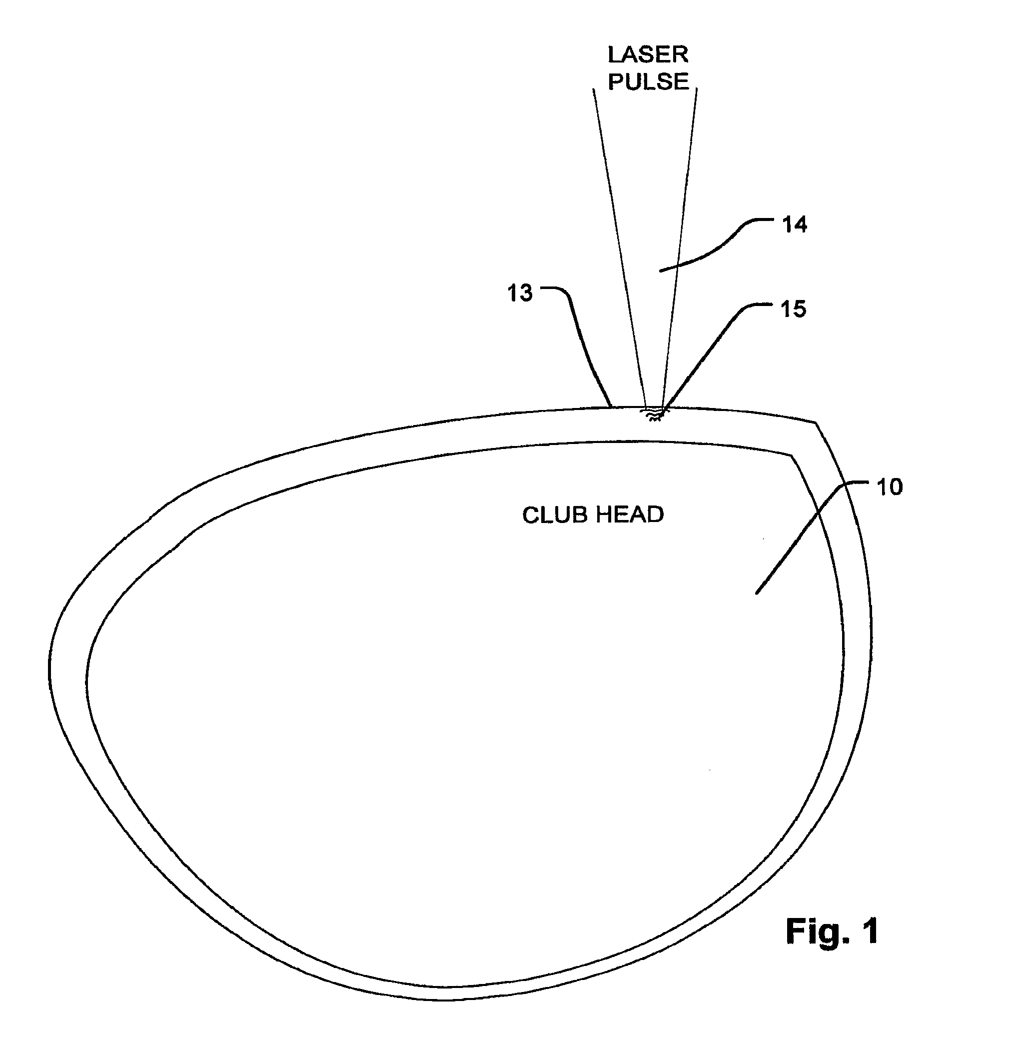
A method of manufacturing a driver, or other types of golf club, includes inducing residual compressive stress by high intensity laser shock peening to form an array of laser shock peened impact zones on the club face. Laser pulses having irradiance greater than 4 GW / cm2, with spot size greater than 4 mm2 are used, including a pulse with on the order of 16 ns, with spot size greater than 9 mm2. Residual compressive stress of more than 400 MPa penetrating with a depth of more than 0.2 mm are imparted, without increased hardening in or damage to the face of the club. Laser shock peening a pattern that covers an interior area leaves the perimeter unpeened, inducing a stress gradient between interior area and the perimeter of the club face. Multiple layers of arrays of laser shock impact zones are applied on the club. The technology is readily applied to assembled club heads.

Description

REFERENCE TO RELATED APPLICATION[0001]The benefit of U.S. Provisional Application No. 60 / 804,775, filed 14 Jun. 2007 is claimed, and such application is incorporated by reference as if fully set forth herein.BACKGROUND OF THE INVENTION[0002]1. Field of the Invention[0003]The present invention relates to an improved golf club, to an improved method for manufacturing a golf club, and more specifically to conditioning the impact face of a golf club with deep compressive stress using laser peening.[0004]2. Description of Related Art[0005]Shot peening has been suggested for club faces to provide better control and increased distance for golf shots. See, U.S. Pat. No. 5,487,543 by Funk. In particular, Funk describes shot peening the face of a club to impart residual compressive stress and harden the surface of the club, and claims that doing so improves the feel of the club by reducing vibration. Funk suggests that shot peening reduces the coefficient of friction of, and hardens, the club...

Claims


Application Information

Patent Timeline
Patent Type & Authority Patents(United States)
IPC IPC(8): A63B53/04
CPCA63B53/04A63B53/0466A63B2053/0445A63B2053/0416A63B2053/0408A63B53/0408A63B53/0416A63B53/0445A63B60/00
Inventor HACKEL, LLOYD A.RANKIN, JONTRUONG, CHANH H.DANE, C. BRENTHARRIS, JR., FRITZ B.
Owner METAL IMPROVEMENT CO INC
Learn More