Method for producing concrete prefinished parts

a technology of prefabricated parts and prefabricated parts, which is applied in the manufacture of final products, manufacturing tools, machines/engines, etc., can solve the problems of insufficient setting, risk of flaws or inadequate and the one-on-one placement of prefabricated parts on the other side of the wall, so as to achieve the effect of facilitating and accelerating the erection of pylons or towers

Active Publication Date: 2013-12-03
WOBBEN ALOYS
View PDF71 Cites 6 Cited by
  • Summary
  • Abstract
  • Description
  • Claims
  • Application Information

AI Technical Summary

Benefits of technology

[0007]In accordance with one aspect of the present disclosure a process is provided for producing precast concrete parts, which permits easier and faster erection of a pylon or tower from the precast concrete parts, with a quality that remains consistently high.
[0017]As the precast concrete parts already leave the factory with plane-parallel join surfaces there is no need for post-treatment of the precast concrete parts on the building site. The precast concrete parts can thus be assembled to constitute a pylon without delay. In particular the step of applying an equalization material is omitted, and as a result, besides eliminating possible sources of error, the operating procedure on the building site is also accelerated and to a large extent made independent of the weather. The process according to the present disclosure provides a uniform quality for the precast concrete parts as complete production takes place in the factory under controlled conditions with quality assurance. In particular construction of the precast concrete parts to form a pylon can take place more quickly as there is no longer any need for any post-treatment operation or application of an equalization layer on the building site.

Problems solved by technology

When constructing high towers or pylons based on prefabricated segment parts or precast concrete parts, it can happen, because of production tolerances, that precast concrete parts which have to be placed one upon the other do not fit together in the optimum fashion.
If those minimum demands are not met or if the equalization layer is incorrectly applied then there is the risk of flaws or inadequate setting and so forth.

Method used


Image

  • Method for producing concrete prefinished parts
  • Method for producing concrete prefinished parts
  • Method for producing concrete prefinished parts

Examples


Embodiment Construction

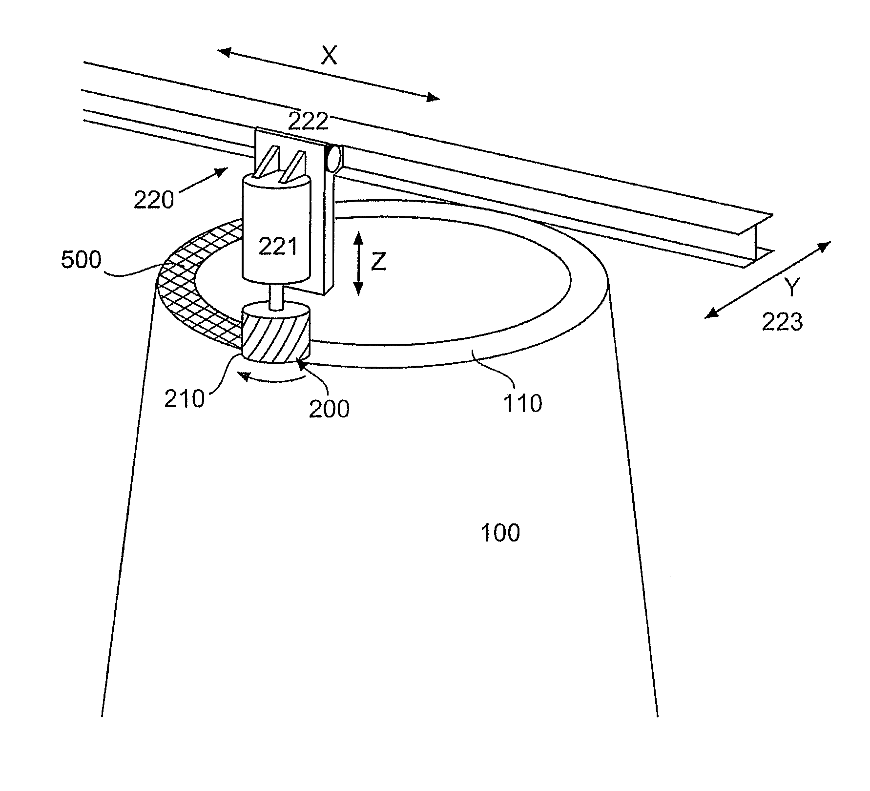
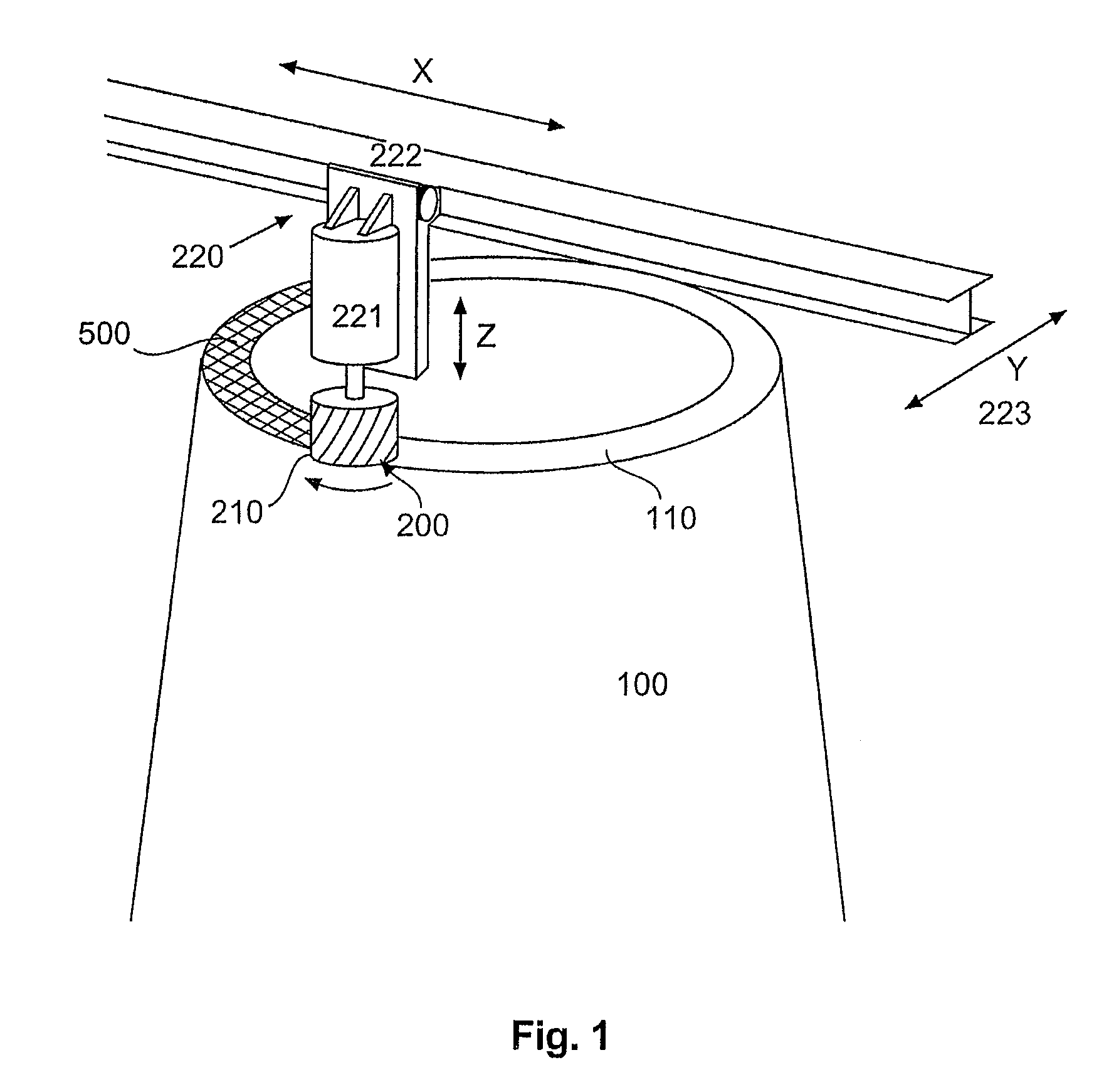
[0026]FIG. 1 shows a perspective view of a precast concrete part and a removal unit in accordance with the first embodiment. The precast concrete part 100 has a join surface or a flange 110, to which an equalization layer 500 is applied. In the first embodiment the removal unit 200 is in the form of a milling unit having a milling head 210 and a displacement unit 220. The displacement unit 220 has a Z-displacement unit 221 for displacement in the Z-direction, an X-displacement unit 222 for displacement in the X-direction and a Y-displacement unit 223 for displacement in the Y-direction. The milling head 210 can be accurately controlled by the X-, Y- and Z-displacement units so that the milling head 210 can remove the equalization layer 500 on the join surface or the flange 110 of the precast concrete part 100 in that way as soon as the equalization layer has reached a minimum strength required for the mechanical processing operation so that the join surface or the flange 110 is plan...


PUM

PropertyMeasurementUnit
thicknessaaaaaaaaaa
strengthaaaaaaaaaa
displacementaaaaaaaaaa

Abstract

There is provided a process for producing precast concrete parts, in particular pylon segments. Concrete is poured into a casting mold with a planar bottom for producing a planar underside. After the concrete has reached at least a minimum strength an equalization layer is applied to a join surface of the precast concrete part that is opposite to the underside. As soon as the equalization layer has reached the minimum strength, the precast concrete part is placed on a horizontally oriented surface and the equalization layer on the top side is removed in a plane-parallel relationship with the underside.

Description

BACKGROUND[0001]1. Technical Field[0002]The present disclosure concerns a process for producing precast concrete parts, a precast concrete part and a wind power installation.[0003]2. Description of the Related Art[0004]When constructing high towers or pylons based on prefabricated segment parts or precast concrete parts, it can happen, because of production tolerances, that precast concrete parts which have to be placed one upon the other do not fit together in the optimum fashion.[0005]To avoid that problem typically an equalization layer, for example mortar, is applied on the building site to a join surface or a flange of a precast concrete part, in which case that equalization layer must then harden on the building site, that is to say it must attain a minimum strength. That requires, inter alia, compliance with minimum meteorological demands which are dependent on the material of the equalization layer. If those minimum demands are not met or if the equalization layer is incorre...

Claims


Application Information

Patent Timeline
Patent Type & Authority Patents(United States)
IPC IPC(8): B28B1/16B28B11/08
CPCB28B1/008B28B7/22B28B11/08B28B21/02B28B21/92E04H12/12F03D11/04F05B2230/60F05B2240/912Y02E10/728F03D13/20Y02P70/50Y02E10/72
Inventor HOLSCHER, NORBERT
Owner WOBBEN ALOYS
Why Eureka
Try Eureka