Device to form a leno selvedge

a technology of leno selvedge and device, which is applied in the direction of weaving, textiles, textiles and paper, etc., can solve the problems of inability to use looms, relatively heavy drive, and relatively slow drive, and achieves low risk of wear between the head of the coil and the permanent magnet, simple structural solution, and cost-effective manufacturing

Active Publication Date: 2013-11-26
GEBR KLOCKER
View PDF13 Cites 5 Cited by
  • Summary
  • Abstract
  • Description
  • Claims
  • Application Information

AI Technical Summary

Benefits of technology

[0006]A drive for a device of the type mentioned above that satisfies these requirements is characterized by the fact that the pivot drive comprises a carrier that, while forming an air gap, has at least two permanent magnets spaced above one another and turned towards one another, whereby a movement member is provided in a pivoting manner on one axis of the frame, whereby the movement member has a head with at least one coil, whereby the head is located in the air gap, whereby the movement member at its end opposite the head is connected to the at least one needle pair. This makes it clear that the described drive is formed according to the principle of a stepper motor, whereby such a stepper motor is characterized by a high degree of efficiency, a high speed, and a high resistance to wear.
[0010]The head of the movement member has the coil with two connections. By appropriate repolarization of the voltage source connected to the connections, the head and the coil are now repelled alternately by one side of the opposing magnets, while being attracted by the other side of the opposing magnets. The implementation of this principle leads to an alternating pivoting movement at high frequency. That means that such a drive is particularly suitable for looms with pick counts of 600 to 700 picks per minute or more. Structurally, with respect to the design of the pivot drive, it is provided that the carrier has a circular arc-shaped carrier head with lateral flanges, whereby between the flanges of at least a first permanent magnet and, forming an air gap between it and the first permanent magnet, at least a second permanent magnet is disposed on the carrier head above the first magnet. The second permanent magnet is thereby advantageously arranged on a carrier lid fastened to the flanges. This yields a very simple structural solution that is also cost-effective to manufacture. The drive is also only slightly susceptible to contamination, since the head of the movement member moves in an air gap that is restricted only laterally by the flanges. Since the drive is arranged vertically on the frame of the leno selvedge mechanism, no contamination can collect in the area of the head of the movement member. Any contamination that still collects can easily be blown off. That means that the risk of wear between the head for the coil and the permanent magnets is low.

Problems solved by technology

Such a drive is relatively heavy; this is particularly notable because this drive must be moved using the drive for the heddle shafts.
Moreover, such a drive is relatively slow, that is, such a drive cannot be used for looms with a high number of picks per minute of 700 or more.
Furthermore, an electromagnetic drive is highly inaccurate, so that it cannot be ensured that after each pick the weft thread will be properly tied off.
The efficiency is also low.

Method used


Image

  • Device to form a leno selvedge
  • Device to form a leno selvedge
  • Device to form a leno selvedge

Examples


Embodiment Construction

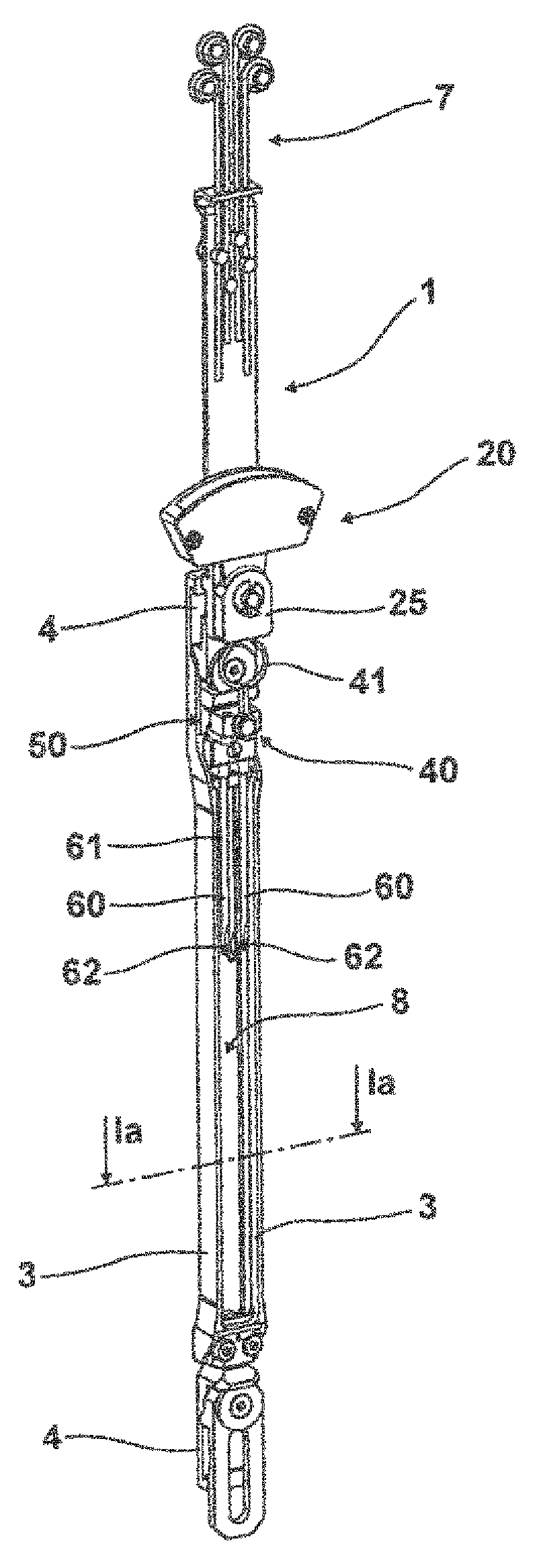
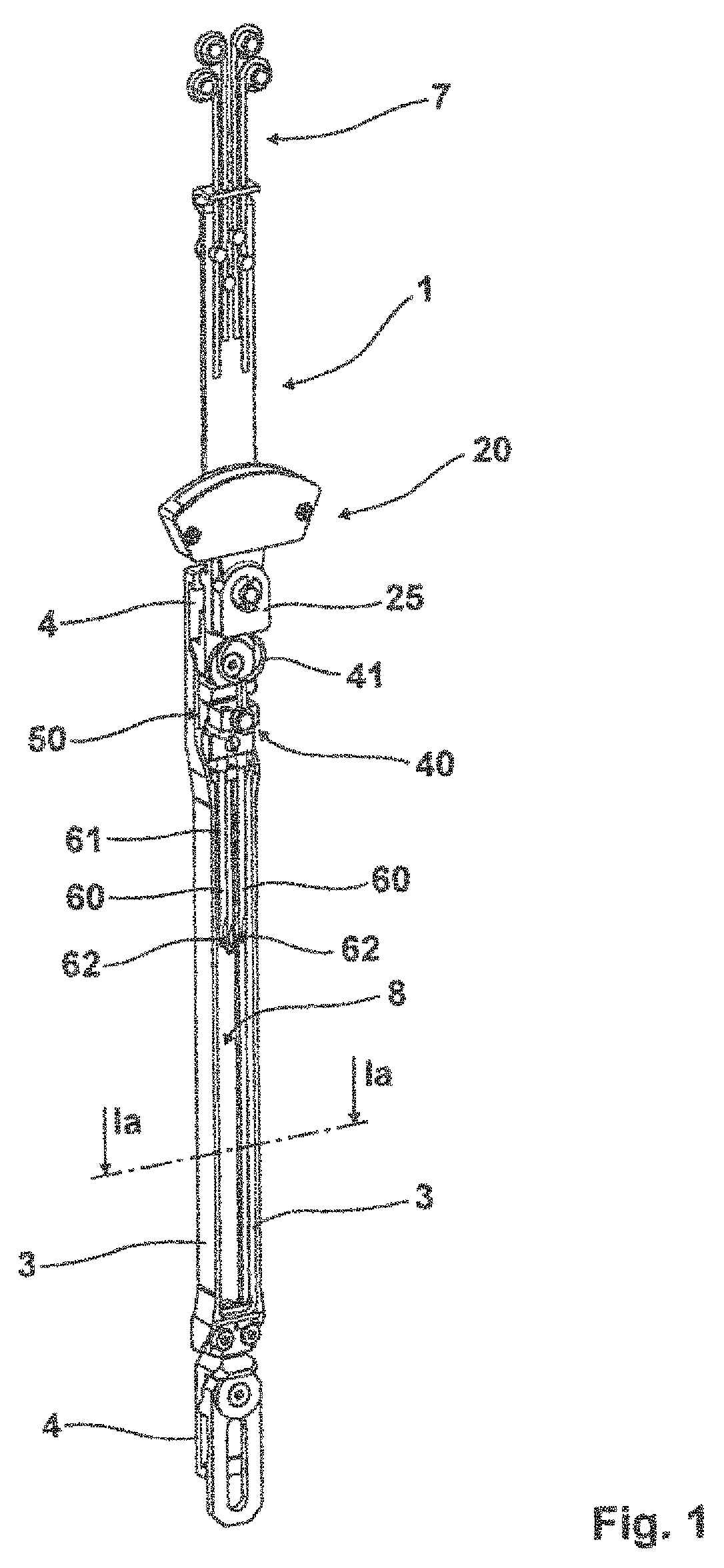
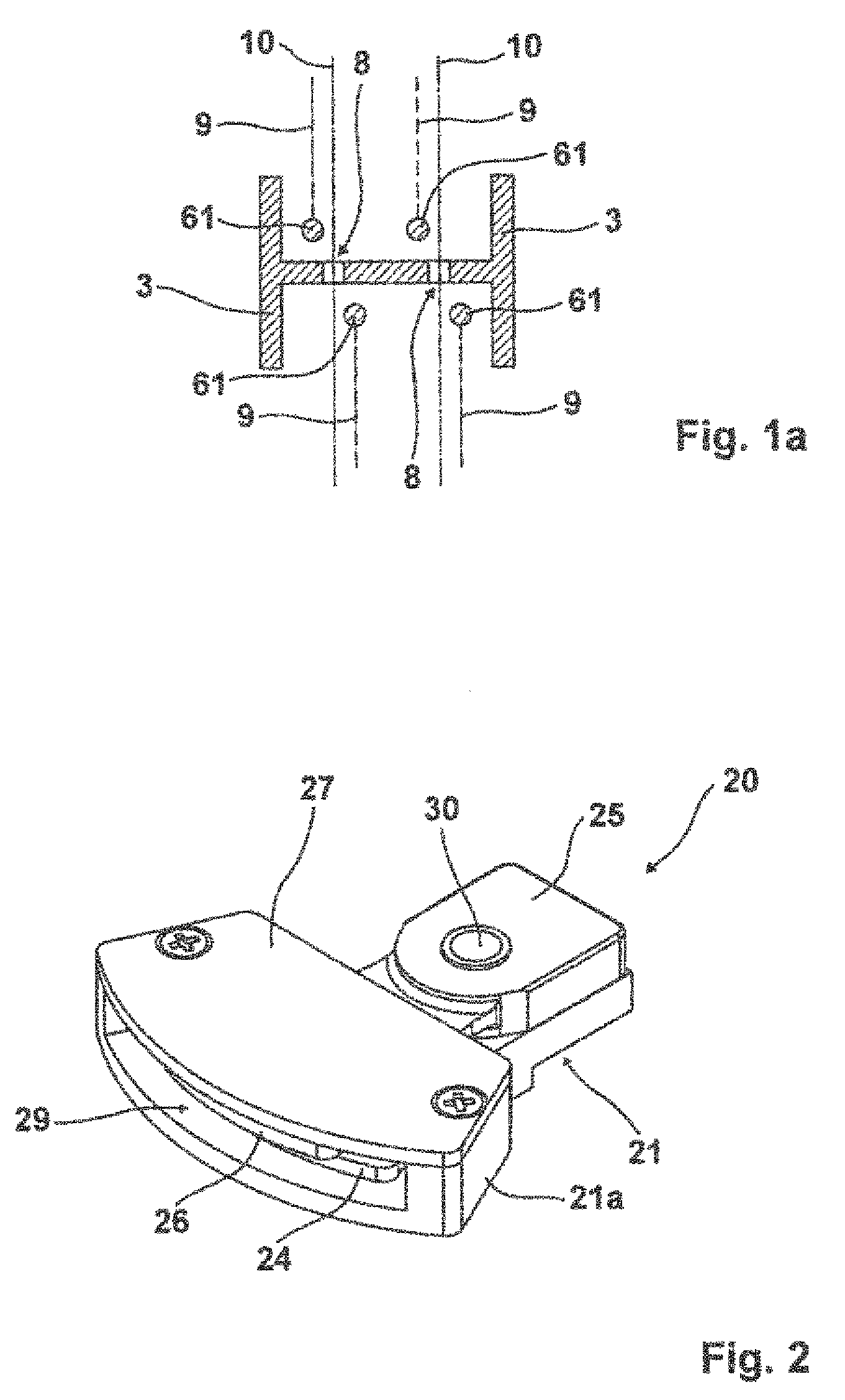
[0018]The leno selvedge device as a whole is denoted with 1. The leno selvedge device 1 has a frame 2 with two frame rails 3 running parallel to one another, whereby the frame supports the pivot drive denoted with 20. The pivot drive shows a movement member 25, whereby the movement member 25 is connected through a coupling arm 30, through a pivoting mechanism 40, and through a diversion mechanism 50, to the two needle pairs 60. The frame 2 furthermore shows at its end at least one shaft holder 4 for fastening to the first heddle shaft. At the upper end, a thread guide 7 is provided with four eyes, whereby four leno threads 9 are correspondingly guided through this thread guide 7 with four eyes, the thread being guided on the bottom through eyes 62 of the needles 61 of each needle pair. The core thread 10 runs between the needles of a needle pair, whereby the thread is being correspondingly guided from the back through a guide into the frame and out to the front. The guide is provide...


PUM


Abstract

A device for the formation of a leno selvedge includes a frame for installation on the heddle shafts of a loom. The frame has at least one needle pair for two leno threads. The needle pair is mounted in the frame so that it can pivot around the longitudinal axis of the frame, and the device includes a pivot drive for pivoting the needle pair.

Description

CROSS-REFERENCE TO RELATE APPLICATIONS[0001]This application claims priority of German Patent Application 20 2011 103 312.4 filed Jun. 30, 2011, the contents of which are incorporated herein by reference.FIELD OF THE INVENTION[0002]The invention concerns a device for the formation of a leno selvedge including a frame for installation on the heddle shafts of a loom, whereby the frame has at least one needle pair for two leno threads, whereby the needle pair is mounted in the frame in such manner that it can pivot around the longitudinal axis of the frame, whereby for the pivoting of at least one needle pair the device has a pivot drive.BACKGROUND OF THE INVENTION[0003]DE-A-1814269 discloses a selvedge apparatus of the type cited above characterized by a frame, whereby at least one needle pair is placed in the frame and whereby the needle pair is oriented in parallel to the longitudinal axis of the frame and can also pivot around the longitudinal axis of the frame. The frame itself is...

Claims


Application Information

Patent Timeline
Patent Type & Authority Patents(United States)
IPC IPC(8): D03C7/06D03C7/00D03C13/00
CPCD03C7/00D03C7/06D03D5/00
Inventor SCHWEMMLEIN, CHRISTOPHHOCKEMEYER, KURT
Owner GEBR KLOCKER
Why Eureka
Try Eureka