
Evaporator with internal restriction

a technology of internal restriction and evaporator, which is applied in the direction of branching pipes, refrigeration components, baking ovens, etc., can solve the problems of only partially successful use of internal baffles in reducing vapor fluctuation, undesirable variation in the thickness of the condensed liquid layer, and fluctuation of the amount of liquid transformed into the vapor phase, so as to reduce the impact of any variation in the atomization process and increase the pressure of the evaporator

Active Publication Date: 2013-11-26
SAMSUNG DISPLAY CO LTD
View PDF421 Cites 0 Cited by
  • Summary
  • Abstract
  • Description
  • Claims
  • Application Information

AI Technical Summary

Benefits of technology

The solution provides a cost-effective and efficient means to achieve stable evaporator pressure and uniform film deposition, allowing for controlled film thickness variations and expanded compatibility with various monomer blends by adjusting the collar's aperture size.

Problems solved by technology

One problem with this process is that the atomization process is not perfectly constant, which results in fluctuations of the amount of liquid transformed into the vapor phase over time.
Fluctuations in the amount of vapor (as measured by the pressure in the evaporator) result in variation of the flux reaching the substrate, causing an undesirable variation in the thickness of the condensed liquid layer.
However, the use of internal baffles has been only partially successful in reducing the vapor fluctuation.
Moreover, this method adds complexity and expense to the evaporator fabrication.
This reduces the overall time for the discrete coating process and increases process throughput for manufacture.
Although this does reduce the time for the evaporator to reach a steady-state pressure, the machining tolerances of the vapor nozzle become more difficult to achieve, making it more expensive and difficult to fabricate components.

Method used


Image

  • Evaporator with internal restriction
  • Evaporator with internal restriction

Examples


Embodiment Construction

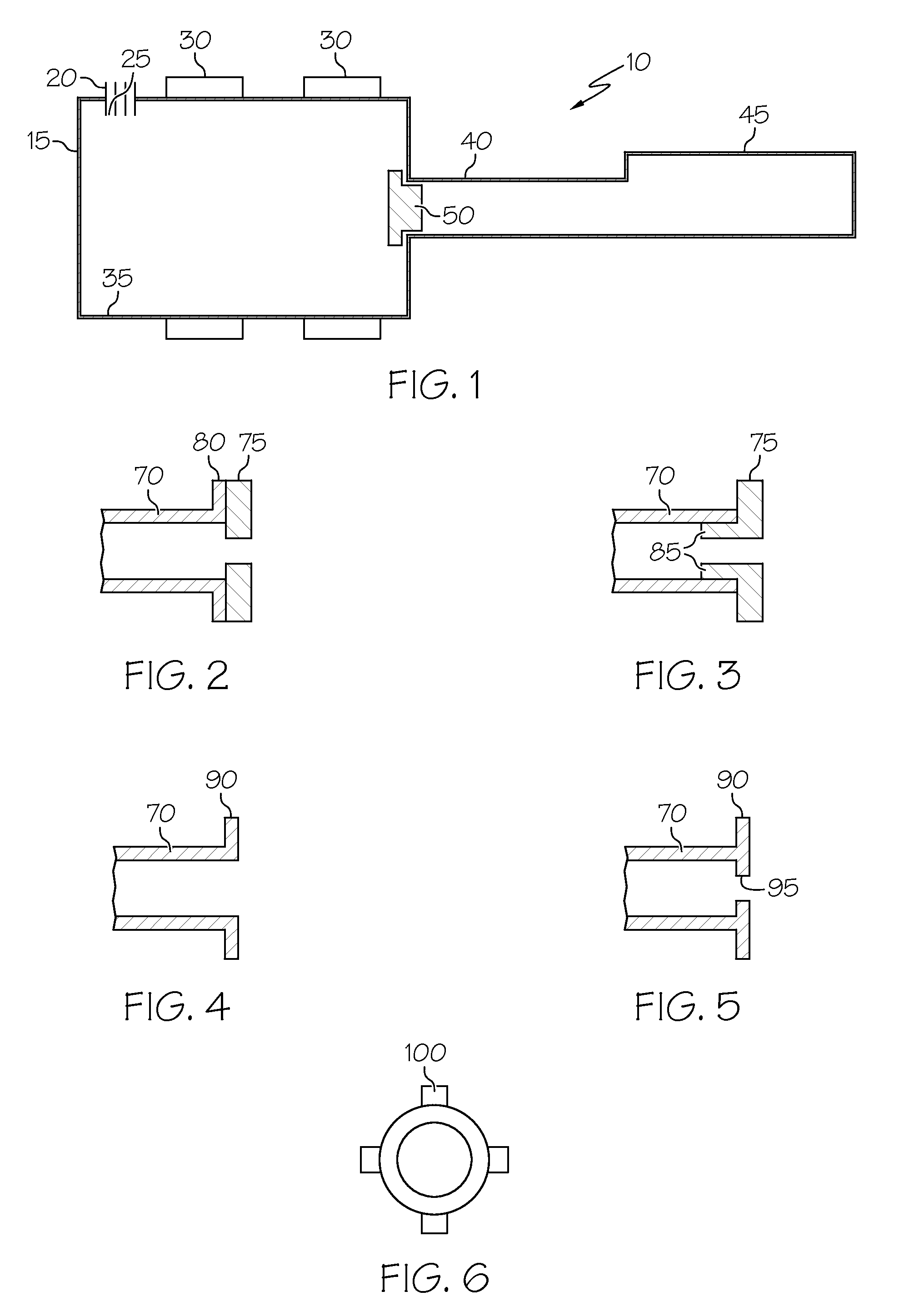
[0014]The conductance through the nozzle is an important characteristic in reducing the variation in the amount of vapor reaching the substrate. Conductance is the amount of vapor that can pass through an opening for a given pressure differential. The easiest way to change the conductance is to vary the diameter of the opening. Alternatively, methods using tubes or closely spaced parallel plates can also be used.

[0015]In one embodiment, there is a collar located between the evaporation chamber and the vapor nozzle through which the vapor exits onto the substrate. The collar forms a constriction, such as a small aperture, which is designed to match the equivalent restriction that had previously been obtained by narrowing the vapor nozzle exit. The result is that the evaporator pressure is increased while the vapor nozzle exit width remains unchanged. This improves the stability of the evaporator pressure with regard to variations in the atomization process because there is much more ...


PUM

PropertyMeasurementUnit
pressureaaaaaaaaaa
conductanceaaaaaaaaaa
cross-sectional areaaaaaaaaaaa

Abstract

An evaporator includes a vaporization chamber having a monomer inlet and a vapor outlet. There is a vapor nozzle in the vapor outlet. The evaporator also includes a collar positioned between the vaporization chamber and the vapor nozzle which increases the pressure in the evaporation chamber while the conductance through the nozzle is substantially unchanged.

Description

[0001]The invention relates generally to evaporators for flash evaporation, and more particularly to an evaporator having improved evaporator pressure stability and film uniformity.BACKGROUND OF THE INVENTION[0002]Flash evaporation of a liquid (single or multi-component) uses an ultrasonic nozzle to atomize the liquid into small droplets which are then dispersed in a container maintained at elevated temperature (evaporator). When the droplets contact the walls of the evaporator, they instantaneously transform to the vapor state without boiling. This process eliminates the separation or distillation of the individual components of the liquid and maintains the equivalent composition of the liquid in the vapor phase. The flash evaporation process is generally described, for example, in U.S. Pat. Nos. 4,954,371, and 4,842,893, which are incorporated herein by reference.[0003]One problem with this process is that the atomization process is not perfectly constant, which results in fluctua...

Claims


Application Information

Patent Timeline
Patent Type & Authority Patents(United States)
IPC IPC(8): F25B41/06F24C7/10F16L5/00F25B39/02A21B1/00A62C31/02
CPCB01B1/06C23C14/243C23C16/4485C23C16/45563B05B17/06Y10S165/911B01D1/16B01D3/06
Inventor BOESCH, DAMIENROSENBLUM, MARTIN
Owner SAMSUNG DISPLAY CO LTD
Learn More