
System and methods for an automated sun glare block area and sunshield in a vehicular windshield

a technology of automatic sun glare block and vehicle windshield, which is applied in the direction of roofs, process and machine control, instruments, etc., can solve the problems of causing highway havoc, reducing the visibility of vehicles, so as to reduce the minimum area, clear and unobstructed the effect of the road, and reducing the visibility

Inactive Publication Date: 2013-11-19
KWOK ANGELA KAREN
View PDF10 Cites 18 Cited by
  • Summary
  • Abstract
  • Description
  • Claims
  • Application Information

AI Technical Summary

Benefits of technology

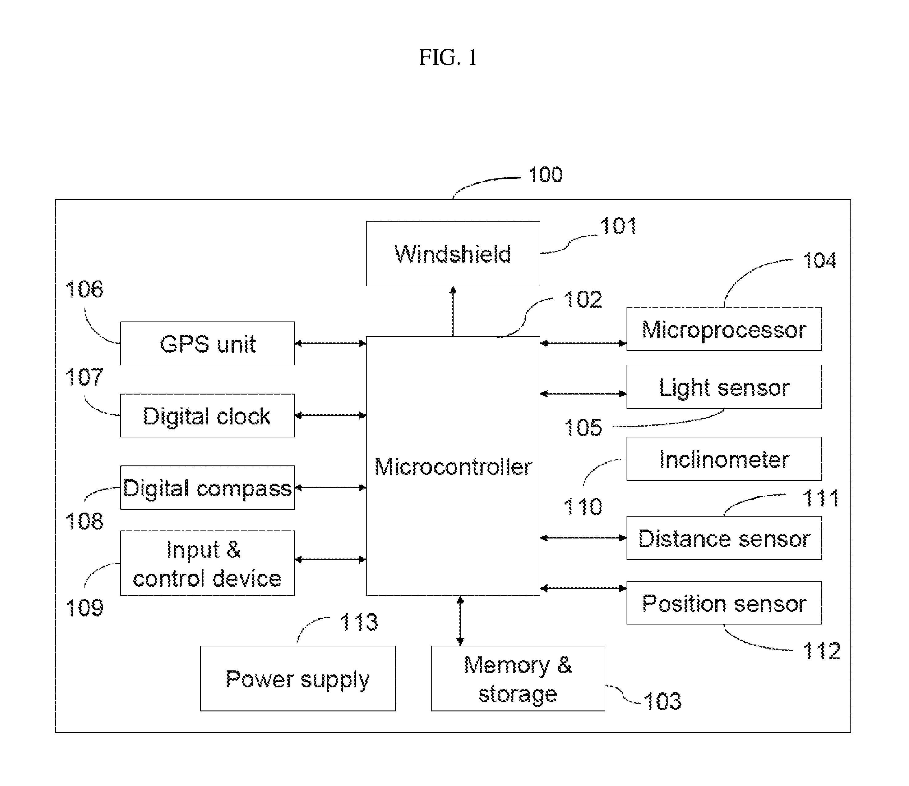
The proposed system in this patent aims to offer a solution for drivers who encounter intense sun glare while driving. The system can detect the precise position of sun glare on the windshield and create a borderless sun glare block area that offers more comfort to the driver's eyes. The system is automatic and can be operated without any preliminary requirements from the driver. The technical effects of this system include improved driving safety and comfort for drivers.

Problems solved by technology

It causes fatal accidents and injuries, creates highway havoc, and drastically slows traffic.
The situation is worst during the height of morning and evening commutes for east- and west-bound traffic, respectively.
When the sun directly perches on the horizon, a sudden, direct flash of sunlight lasting a mere decisecond can easily blind the driver.
However, these visor extensions provide protection only if the sun glare is in the top region of the windshield and they may obstruct the driver's view.
When the area of intense sun glare lies in the lower region of the windshield, the driver has to raise one hand to shield the sun's piercing light and keep only one hand on the steering wheel, causing a dangerous situation.
Although these visors can move in both the vertical and horizontal directions, they still have the shortcomings of a visor because they are inconvenient and may divert the driver's attention away from the road.
However, these also require extensive hardware addition and modification and obstruct the driver's view.
However, none of the aforementioned systems provide a method that is automatic or darkens only a specific area in the windshield needed to block the sun glare.
Although it is automatic with an optical sensor, the device is cumbersome.
All the inventions noted in this paragraph unnecessarily darken areas of the windshield that are not in the path of the sun glare to the driver's eyes, which will inadvertently obstruct the driver's view.
However, it requires a sophisticated and expensive sensor system.
However, this solution has the disadvantages of being expensive, in that extra sensor and camera hardware is needed to detect not only the driver's eye position, but also the light source position.
First, the patent does not disclose or describe the details—only the conceptual idea—on how the information from the navigation and ephemeris systems and data on the general location of the driver's eyes are translated into pixels on the electro-optical element.
This would be an unnecessary strain on the driver.
Third, the system does not consider the slope (inclination or declination) of the road.
One of the most dangerous situations for an accident is when there is an abrupt change in the slope of the road and the sun glare will be blinding.
Fourth, the patent's method provides only an estimation of the area for opacity to be attenuated because it does not consider the windshield tilt angle, which can vary substantially among different makes and models of motor vehicles.

Method used


Image

  • System and methods for an automated sun glare block area and sunshield in a vehicular windshield
  • System and methods for an automated sun glare block area and sunshield in a vehicular windshield
  • System and methods for an automated sun glare block area and sunshield in a vehicular windshield

Examples


Embodiment Construction

[0045]The invention is described hereinafter in detail with reference to the accompanying drawings, which forms a part of this specification. This detailed description focuses on an innovative method to accurately calculate the precise position and opacities of the sun glare block area and a first-of-its-kind system to display it in the windshield of a motor vehicle.

[0046]As stated in the background on the calculation of the sun glare position on the windshield, prior arts do not disclose or provide a detailed description on how to obtain the precise position of the sun glare on the windshield. Some prior arts provide only a conceptual approach on the estimation or approximation of the sun glare position on the windshield assuming a fixed position of the driver's eyes. Whenever the driver has a small movement of his or her head during driving, the sun glare block area will cover only part of the sun glare for the driver's eyes. In this invention, an accurate calculation of the preci...


PUM


Abstract

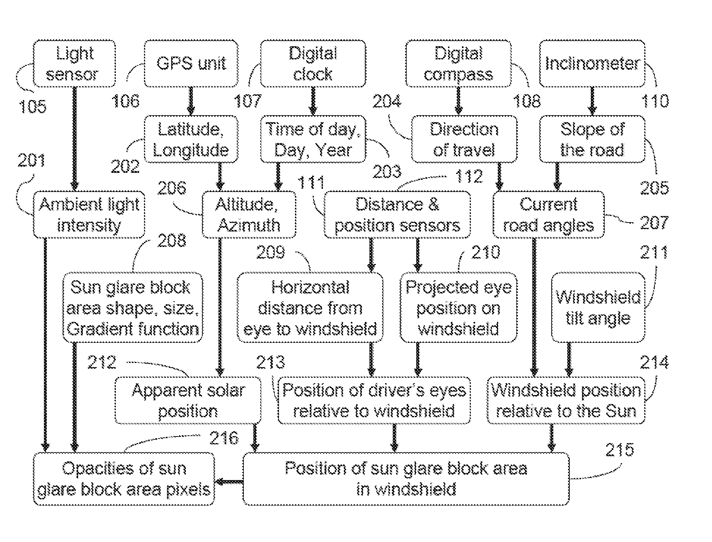
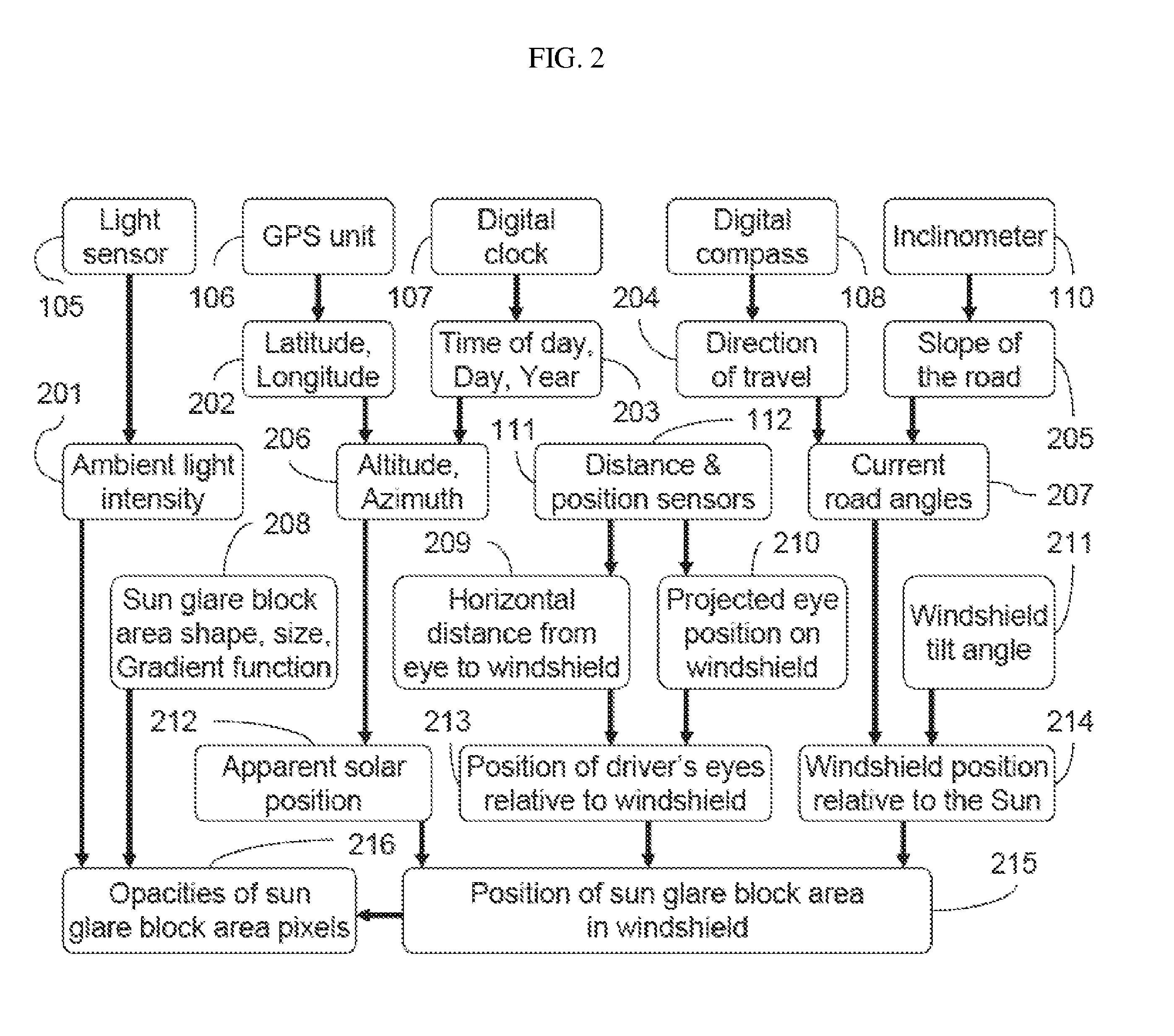
A system and methods for the automated display of a borderless sun glare block area and sunshield in a windshield, which can be made of electrochromatic glass, in a motor vehicle driven at any time and at any location on earth is presented. The first method, which accurately calculates the precise position of the sun glare block area, is based on the apparent solar position, the direction of travel relative to the true North, the slope of the road, the windshield tilt angle, and the dynamic position of the driver's eyes. It uses sets of different formulas depending on the position of the sun glare on the windshield and the slope of the road. The second method calculates the changing opacities of the borderless sun glare block area, whose opacity decreases from its center to its edge and matches that of the sunshield, based on the ambient light intensity.

Description

CROSS REFERENCE TO RELATED APPLICATIONS[0001]Not applicable.STATEMENT REGARDING FEDERALLY SPONSORED RESEARCH OR DEVELOPMENT[0002]Not applicable.BACKGROUND OF THE INVENTION[0003]1. Technical Field of the Invention[0004]This invention relates generally to sun glare on a vehicular windshield, and more particularly to providing a method for the calculation of the sun glare position and a system for displaying a darkened area in the windshield to reduce the intensity of the sun glare or to block the sun glare from the driver's eyes.[0005]2. Description of the Related Art[0006]Sun glare is one of the most overlooked dangers of driving. It causes fatal accidents and injuries, creates highway havoc, and drastically slows traffic. The situation is worst during the height of morning and evening commutes for east- and west-bound traffic, respectively. When the sun directly perches on the horizon, a sudden, direct flash of sunlight lasting a mere decisecond can easily blind the driver. Consider...

Claims


Application Information

Patent Timeline
Patent Type & Authority Patents(United States)
IPC IPC(8): B60R22/00G06F7/00G06F17/00E05F15/00G05D1/00G05D3/00
CPCG02B27/01B60J3/04G02B2027/0118G02B2027/014
Inventor KWOK, ANGELA KAREN
Owner KWOK ANGELA KAREN
Learn More