Method for adaptively matching microphones of a hearing system as well as a hearing system

a technology of adaptive matching and hearing system, applied in the direction of deaf-aid sets, microphone signal combination, electrical apparatus, etc., can solve the problems of insufficient phase matching of available microphones to achieve satisfactory beamforming, and inability to accurately match microphones, so as to achieve effective beamforming and improve speech intelligibility

Active Publication Date: 2013-11-19
SONOVA AG
View PDF11 Cites 1 Cited by
  • Summary
  • Abstract
  • Description
  • Claims
  • Application Information

AI Technical Summary

Benefits of technology

[0008]Hearing systems utilize two microphones to do beamforming. Beamforming is known as a very effective way to improve speech intelligibility for hearing impaired persons wearing a hearing system. To enable effective beamforming, the microphones resp. the signal paths up to a beamformer processing unit have to be well matched in phase and magnitude over the frequency range of interest.
[0018]applying the correction factor to the signals of the microphones of the hearing system in order to reduce a difference between the true direction and a corrected estimated direction obtained via corrected microphone signals.
[0019]Thereby, the performance of the beamformer can be improved to a large extent. This is in particular true with regard to the low frequency behavior of the beamformer. In addition, static calibration methods to match the microphones in production or during the fitting process can be avoided.
[0026]In further embodiments of the method according to the present invention, a speech detector is used to determine whether a single broadband sound source is present. With the speech detector, a single sound source can easily be determined. Such a sound source is sufficiently broadband and originates from a single location. Therefore, it can very be used for adapting the microphones.
[0033]means for applying the correction factor to the input signals of the microphones in order to reduce a difference between the true direction and a corrected estimated direction obtained via corrected input signals.

Problems solved by technology

Unfortunately, the available microphones are not sufficiently matched in phase to achieve a satisfactory beamforming performance at low frequencies without further matching methods.
Wrong assumption for the model or insufficient models result in an imprecise beamformer.

Method used


Image

  • Method for adaptively matching microphones of a hearing system as well as a hearing system
  • Method for adaptively matching microphones of a hearing system as well as a hearing system
  • Method for adaptively matching microphones of a hearing system as well as a hearing system

Examples


Embodiment Construction

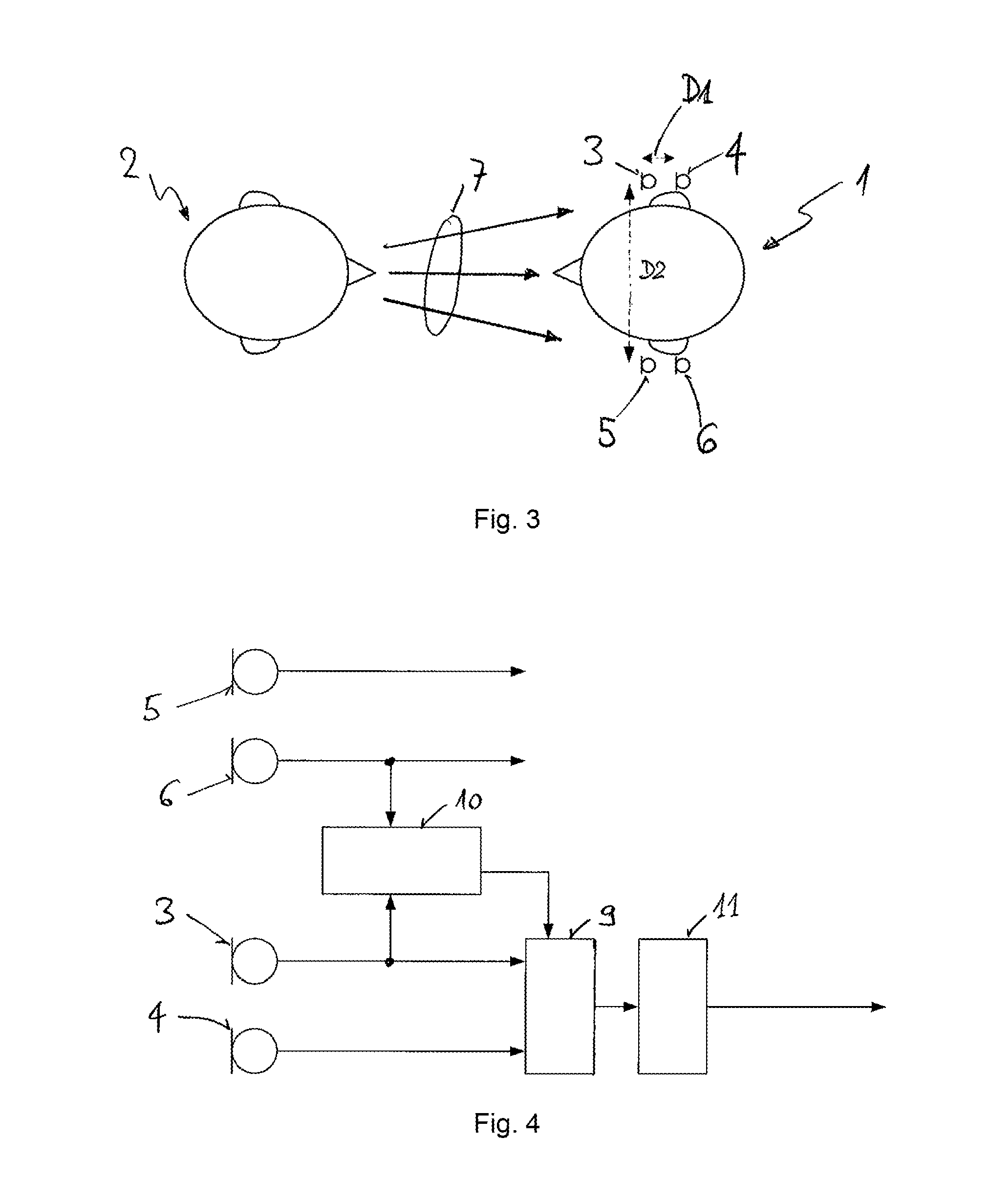
[0049]FIG. 1 shows a common situation which is suitable to perform a microphone matching according to the present invention. The situation is characterized in that a hearing system user 1 is confronted with a single sound source 2. The single sound source 2 is a person speaking to the hearing system user 1. The hearing system user 1 wears a hearing device in one of his ears—also known as monaural hearing system—, the hearing device comprising two microphones 3 and 4. The microphones 3 and 4 or a signal path up to a beamformer, respectively, have to be matched in phase and magnitude over a frequency range of interest to enable effective and accurate beamforming. Thereby, it has been shown that a phase matching is particularly important for lower frequencies, i.e. for frequencies below 1 kHz, for example, than for higher frequencies, i.e. for frequencies above 1 kHz, for example. Since microphones are usually sufficiently well matched by the manufacturer above approximately 1 kHz, pha...


PUM


Abstract

A method and a hearing system for adaptively matching microphones (3, 4) of a hearing system. The method comprising the steps of determining a true direction towards a sound source, determining an estimated direction towards the sound source using microphones (3, 4) of the hearing system, comparing the true direction with the estimated direction to obtain a correction factor, applying the correction factor to the signals of the microphones (3, 4) of the hearing system in order to reduce a difference between the true direction and a corrected estimated direction obtained via corrected microphone signals.

Description

CROSS-REFERENCE TO RELATED APPLICATIONS[0001]Not ApplicableSTATEMENT REGARDING FEDERALLY SPONSORED RESEARCH OR DEVELOPMENT[0002]Not ApplicableINCORPORATION-BY-REFERENCE OF MATERIAL SUBMITTED ON A COMPACT DISC[0003]Not ApplicableBACK GROUND OF THE INVENTION[0004](1) Field of the Invention[0005]The present invention is related to a method for adaptively matching microphones of a hearing system as well as to a hearing system.[0006](2) Description of Related Art Including Information Disclosed Under 37 CFR 1.97 and 1.98[0007]Not ApplicableBRIEF SUMMARY OF THE INVENTION[0008]Hearing systems utilize two microphones to do beamforming. Beamforming is known as a very effective way to improve speech intelligibility for hearing impaired persons wearing a hearing system. To enable effective beamforming, the microphones resp. the signal paths up to a beamformer processing unit have to be well matched in phase and magnitude over the frequency range of interest.[0009]Unfortunately, the available m...

Claims


Application Information

Patent Timeline
Patent Type & Authority Patents(United States)
IPC IPC(8): H04R25/00
CPCH04R29/006H04R3/005H04R25/407
Inventor KRAMER, MICHAELROECK, HANS-UELI
Owner SONOVA AG
Why Eureka
Try Eureka