Magnetic microvalve using metal ball and method of manufacturing the same

a technology of magnetic micro valves and metal balls, which is applied in the direction of valves, other domestic objects, mechanical devices, etc., can solve the problems of expensive materials such as silicone, limited flow and pressure, and manufacturing methods and control, so as to facilitate the manufacturing of such devices, improve the bonding of upper and lower substrates, and facilitate the effect of manufacturing

Inactive Publication Date: 2013-11-19
ELECTRONICS & TELECOMM RES INST
View PDF39 Cites 4 Cited by
  • Summary
  • Abstract
  • Description
  • Claims
  • Application Information

AI Technical Summary

Benefits of technology

[0011]An aspect of the present invention provides a magnetic microvalve using a metal ball and a method of manufacturing the same that can improve the bonding of upper and lower substrates by locally disposing a PDMS / metal ball combination in a lower substrate, provide quick and easy control by using magnetic force, and facilitate the manufacturing thereof.

Problems solved by technology

However, micropumps and microvalves in the related art may have complicated actuating methods, manufacturing methods and control thereof, require expensive materials such as silicone, or may be limited in terms of flow and pressure while being actuated.
Furthermore, as for PDMS pneumatic valves or PDMS magnetic valves using PDMS (polydimethylsiloxane) according to the related art, as a PDMS layer needs to be applied over the entire area of a chip, problems may occur when electrodes are installed, when upper and lower substrates are bonded to each other, or when a sample is absorbed.

Method used


Image

  • Magnetic microvalve using metal ball and method of manufacturing the same
  • Magnetic microvalve using metal ball and method of manufacturing the same
  • Magnetic microvalve using metal ball and method of manufacturing the same

Examples


Embodiment Construction

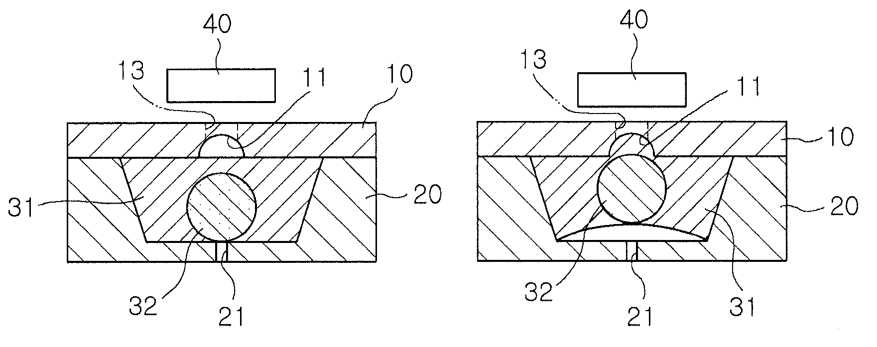
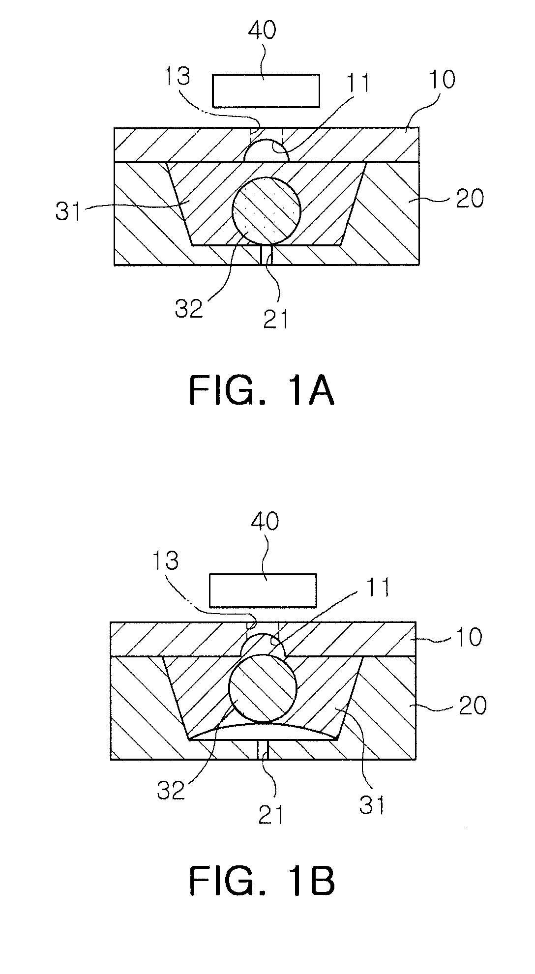
[0032]Exemplary embodiments of the present invention will now be described in detail with reference to the accompanying drawings. The invention may, however, be embodied in many different forms and should not be construed as being limited to the embodiments set forth herein. Rather, these embodiments are provided so that this disclosure will be thorough and complete, and will fully convey the scope of the invention to those skilled in the art. In the drawings, the shapes and dimensions may be exaggerated for clarity, and the same reference numerals will be used throughout to designate the same or like components.

[0033]It will be understood that when an element is referred to as being “connected with” another element, it can be directly connected with the other element or intervening elements may also be present. In contrast, when an element is referred to as being “directly connected with” another element, there are no intervening elements present. In addition, unless explicitly des...


PUM

PropertyMeasurementUnit
angleaaaaaaaaaa
arbitrary angleaaaaaaaaaa
magnetic forceaaaaaaaaaa

Abstract

There is provided a magnetic microvalve using a metal ball and a method of manufacturing the same. A magnetic microvalve using a metal ball according to an aspect of the invention may include: an upper substrate having a microchannel serving as a passage through which a fluid moves, a fluid inlet through which the fluid flows into the microchannel, and a fluid outlet through which the fluid, having passed through the microchannel, flows out of the microchannel; a lower substrate having a trench locally provided therein; a PDMS / metal ball combination having a metal ball and PDMS surrounding the metal ball so that the metal ball is located in a central portion thereof, the PDMS / metal ball combination being inserted into the trench provided in the lower substrate; and a magnet located above the microchannel, provided in the upper substrate, and generating magnetic force.

Description

CROSS-REFERENCE TO RELATED APPLICATIONS[0001]This application claims the priority of Korean Patent Application No. 10-2009-0082217 filed on Sep. 1, 2009, in the Korean Intellectual Property Office, the disclosure of which is incorporated herein by reference.BACKGROUND OF THE INVENTION[0002]1. Field of the Invention[0003]The present invention relates to a magnetic microvalve using a metal ball, and more particularly, to a magnetic microvalve using a metal ball and a method of manufacturing the same that can improve the bonding of upper and lower substrates by locally disposing a PDMS / metal ball combination in a lower substrate, provide quick and easy control by magnetic force, and facilitates the manufacturing thereof.[0004]2. Description of the Related Art[0005]In general, in the area of biochips for biochemical analyses, such as DNA chips or protein chips, and lab-on-a-chips based on microfluidics, flow control techniques are required for the stopping, pumping, mixing, distributing...

Claims


Application Information

Patent Timeline
Patent Type & Authority Patents(United States)
IPC IPC(8): F16K31/08
CPCF16K99/0001F16K99/0015F16K99/0026F16K99/0046F16K99/0034F16K2099/0078B81B3/00F16K31/02Y10T29/49425
Inventor CHUNG, KWANG HYOCHOI, YO HANLEE, DAE SIKKIM, YOUNG JUNJUNG, MOON YOUNPARK, SEON HEE
Owner ELECTRONICS & TELECOMM RES INST
Why Eureka
Try Eureka