
Examination stand with improved access for the wheelchair bound patient

a technology for examining tables and wheelchairs, applied in the field of stands, can solve the problems of insufficient lowness, inability to examine patients bound to wheelchairs, and large space limitations of known medical equipment stands, so as to achieve convenient use, low cost, and high quality.

Inactive Publication Date: 2013-11-05
OPHTHALMOLOGY ASSOCS OF NORTHWESTERN OHIO
View PDF5 Cites 4 Cited by
  • Summary
  • Abstract
  • Description
  • Claims
  • Application Information

AI Technical Summary

Benefits of technology

The present invention provides a stand for medical equipment, specifically a rotatable stand for a slit lamp microscope and a phoropter attached to the stand. The stand is designed to be high-quality, low-cost, and easy to use, with special consideration for patients who use wheelchairs. The technical effects of this invention include improved access to medical equipment for patients and ease of use for clinicians.

Problems solved by technology

However, known medical equipment stands have several limitations in the range of patients which can be conveniently examined, especially with respect to patients confined to a wheelchair.
For example, the table is typically too wide to be placed between the arms of a standard wheelchair.
Also, legs connecting the stand to the table were previously designed to work with an examination chair which is much higher than standard wheelchairs, and therefore cannot get low enough to examine a patient bound to a wheelchair.
Moreover, the legs have previously been attached to the table on the underside of the table near the center of the table, such that the legs partially obstructs area below the table, requiring the table to be raised to clear over a patient's lower body, for example.
Clearly, this makes known medical equipment stands inconvenient for wheelchair bound patients.
While some examination stands have examination chairs which are movable along a track, this is not a practical option when the examination room is relatively small, as is often the case with ambulatory surgical facilities.
However, the phoropter (the instrument used by optometrists and ophthalmologists to measure an individuals refractive error and to determine his eyeglass prescription) of many off the shelf ophthalmic examination stands may, in some instances, still be unable to be conveniently accessed by a wheelchair bound patient.

Method used


Image

  • Examination stand with improved access for the wheelchair bound patient
  • Examination stand with improved access for the wheelchair bound patient
  • Examination stand with improved access for the wheelchair bound patient

Examples


Embodiment Construction

[0013]It will be apparent to those skilled in the art, that is, to those who have knowledge or experience in this area of technology, that many uses and design variations are possible for the medical equipment / examination stand disclosed here. The following detailed discussion of various alternative and preferred features and embodiments will illustrate the general principles of the invention with reference to a stand for use with an ophthalmic slit lamp and related ophthalmic equipment. Other embodiments suitable for other applications, such as a stand for use with an ocular blood flow analyzer will be apparent to those skilled in the art given the benefit of this disclosure.

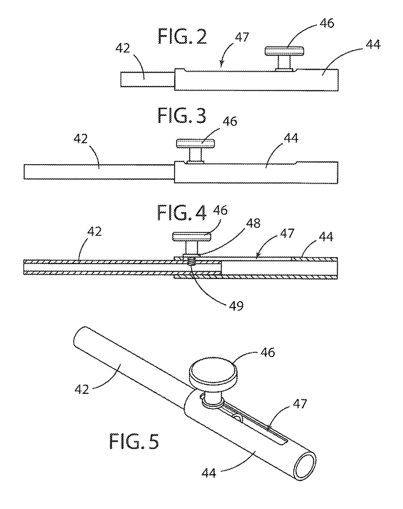
[0014]Referring now to the drawings, FIG. 1 shows a patient examination assembly in accordance with a preferred embodiment. A stand 10, preferably rotatable about a vertical axis, supports medical equipment. In FIG. 1, some of the medical equipment can comprise, for example, a slit lamp biomicroscope 20, mounte...


PUM


Abstract

A patient examination assembly comprises a rotatable stand adapted to mount a slit lamp microscope, and a phoropter attached to the stand by a telescoping arm assembly, comprising an arm and a connector, and the connector comprises a first link and a second link. The first link is telescopeable within the second link.

Description

FIELD OF THE INVENTION[0001]This invention relates to a stand for medical equipment and more particularly to a stand which improves access to the medical equipment for wheelchair bound patients.BACKGROUND OF THE INVENTION[0002]Medical equipment for examination of a patient sometimes comprises an examination chair, an instrument stand which supports some of the medical equipment, and a table connected to the stand via a series of adjustable arms. The table supports additional medical equipment, for example, a slit lamp biomicroscope. The slit lamp is an instrument consisting of a high-intensity light source that can be focused to shine as a slit. It is used in conjunction with a microscope. The lamp helps examination by allowing a doctor to look at the anterior segment, or frontal structures of the human eye, which includes the eyelid, sclera, conjunctiva, iris, natural crystalline lens, and cornea. The binocular slit-lamp examination provides stereoscopic magnified view of the eye s...

Claims


Application Information

Patent Timeline
IPC IPC(8): A61B3/00A61B3/18
CPCA61B19/26A61B3/0075A61B3/0285A61B3/18A61B90/50
Inventor KENDRICK, RONALD M.
Owner OPHTHALMOLOGY ASSOCS OF NORTHWESTERN OHIO
Learn More