
Portable pipe cutter

a portable, pipe cutter technology, applied in the direction of portable lathes, tube shearing machines, manufacturing tools, etc., can solve the problems of bulky and extended grip handle on the portable pipe cutter, and achieve the effect of convenient gripping, easy rotation and operation bare-handed, and firm grip

Active Publication Date: 2013-11-05
YUNG CHI IND
View PDF8 Cites 15 Cited by
  • Summary
  • Abstract
  • Description
  • Claims
  • Application Information

AI Technical Summary

Benefits of technology

This patent describes a portable pipe cutter that has several technical features. The cutter is easy to hold and rotate with one's bare hands, and it has a knife that automatically moves forward. The cutter also has an adjustable space to fit different diameters of metal pipes. Additionally, the cutter has a secure grip on the metal pipes, making it easier to cut through them with steady precision.

Problems solved by technology

Its volume and weight inconvenience its removal, and therefore it is usually disposed at a fixed position.
The extended grip handle disposed on the portable pipe cutter is still bulky, whereas the disc knife and roller disposed on fixed-point operation pipe-cutting mechanism are only applicable to pipes of a fixed size.

Method used


Image

  • Portable pipe cutter
  • Portable pipe cutter
  • Portable pipe cutter

Examples


Embodiment Construction

[0020]The above and further objects and novel features of the invention will more fully appear from the following detailed description when the same is read in connection with the accompanying drawing. It is to be expressly understood, however, that the drawing is for purpose of illustration only and is not intended as a definition of the limits of the invention.

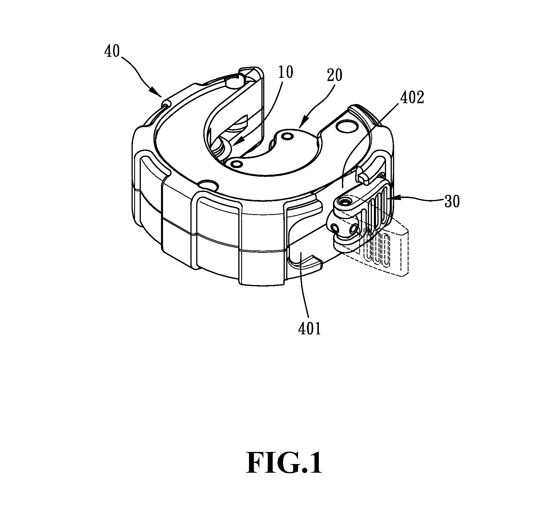
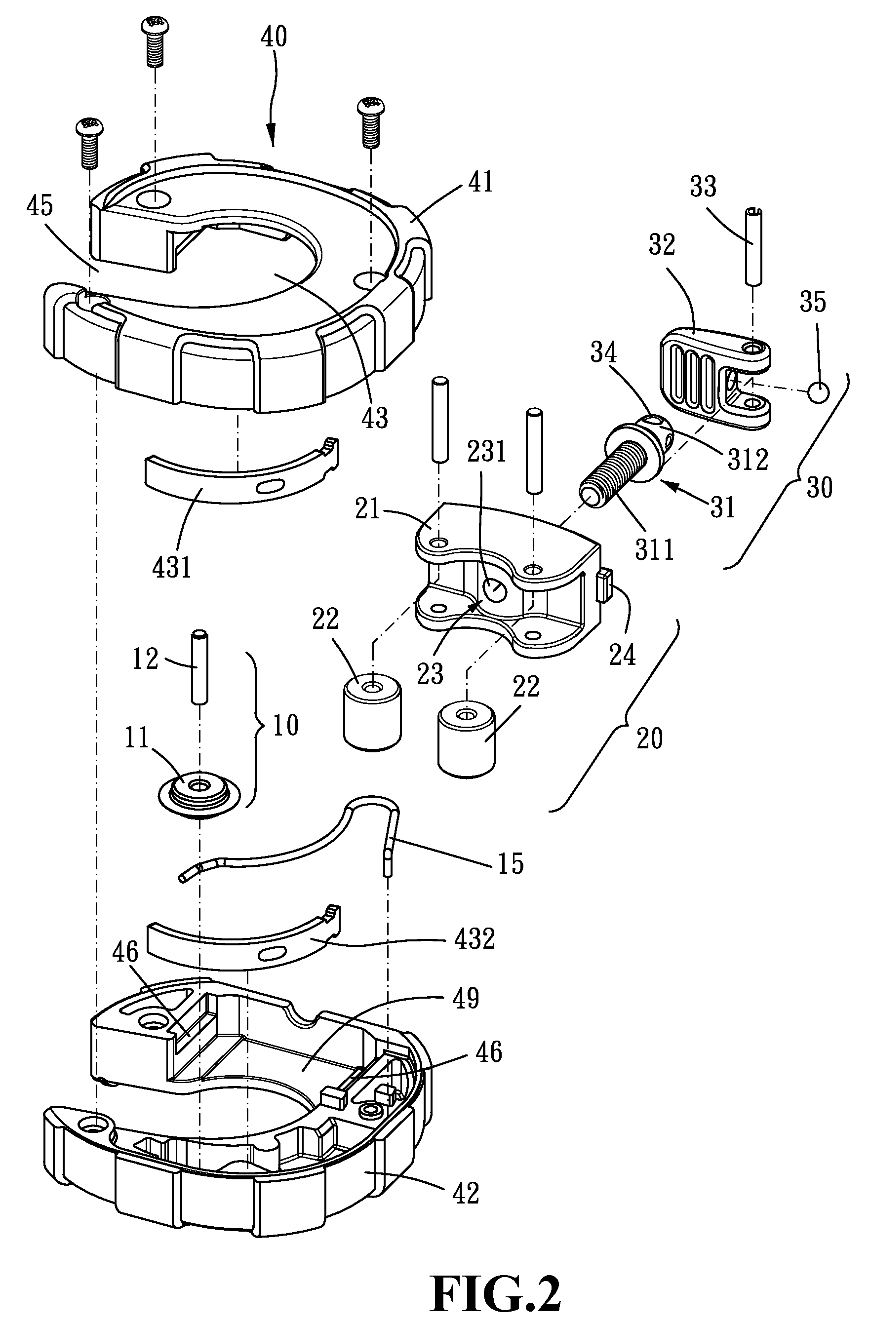
[0021]Referring first to FIGS. 1 to 4, the preferred embodiment of the pipe cutter according to the present invention includes a disc knife set 10, a roller set 20, a driving assembly 30, and a main body 40.

[0022]The disc knife set 10 includes a disc knife 11 and a knife axle 12 piercing through the center of the disc knife 11. The disc knife 11 and the knife axle 12 can freely rotate relative to each other.

[0023]The roller set 20 includes a roller base 21, two rotatable rollers 22 disposed in the front of the roller base 21, and a driving set joint 23 disposed at the back of the roller base 21. The driving set joint 23 is a...


PUM

PropertyMeasurementUnit
angleaaaaaaaaaa
rotationaaaaaaaaaa
flexibleaaaaaaaaaa

Abstract

A pipe cutter comprises a disc knife set and a roller set disposed inside a main body, a driving assembly piercing through the main body and connected to the roller set with a rotating operation component disposed on the exterior of the main body, and a conversion module connecting the main body, driving assembly, and roller set which converts the rotation of the rotating operation component into the linear movement of the roller set to adjust the relative distance between the roller set and the disc knife of the disc knife set and thereby to adapt the pipe cutter to the cutting of metal pipes with different diameters.

Description

BACKGROUND OF THE INVENTION[0001]1. Field of the Invention[0002]The present invention relates to a tool for cutting metal pipes and particularly to a portable pipe cutter which can be gripped and rotated bare-handedly to cut metal pipes.[0003]2. Brief Description of the Related Art[0004]Existing metal pipe cutters can be classified into two types—fixed-point operation type and portable type. A powered cutting tool and a pipe positioning device are usually disposed on the frame of a fixed-point operation pipe-cutting mechanism. This kind of pipe cutter is usually used when cutting hard metal pipes or those with big diameters. Its volume and weight inconvenience its removal, and therefore it is usually disposed at a fixed position.[0005]Portable pipe cutters are usually used when cutting copper pipes, thin-walled metal pipes, or metal pipes with small diameters. Without any powered cutting tool disposed thereon, a portable pipe cutter is relatively smaller than a fixed-point operation...

Claims


Application Information

Patent Timeline
Patent Type & Authority Patents(United States)
IPC IPC(8): B23D21/04B23D21/08
CPCB23D21/08Y10T82/16245Y10T82/22
Inventor HUANG, WU SHENG
Owner YUNG CHI IND
Learn More