Lower power controller for DC to DC converters

a low-power controller and converter technology, applied in the field of dc to dc converters, can solve the problems of disadvantageous high cost and require a more complex circuit structure, and achieve the effects of reducing the number of external components, and saving power consumption

Inactive Publication Date: 2013-10-08
ST ERICSSON SA
View PDF11 Cites 2 Cited by
  • Summary
  • Abstract
  • Description
  • Claims
  • Application Information

AI Technical Summary

Benefits of technology

[0009]It is therefore an object of the present invention to provide a DC to DC converter system capable to operate in PFM mode with a variable on-time, while saving power consumption, being immune to noise at high frequencies, and being designed with a reduced number of external components.
[0023]In another embodiment, the DC to DC converter system may operate in pulse frequency modulation (PFM) mode, such that the first current through the inductive storage element can reach a zero value. Thereby, the occurrence of a right-half plane (RHP) zero can be avoided for getting a better stability of the DC to DC converter system at high currents and during the duty cycles of the switching means, and the inductive storage element can be minimized.
[0028]The first current may preferably have a peak value much greater than the second current delivered by the current source, such that the replica of the first current is carried out by means of a small-signal circuit, which saves power.
[0029]The drive means may be a set-reset flip flop, which is set and reset respectively by a set and reset signal issued from comparator means. Thereby, a digital control means using a high-frequency clock for controlling the set-reset flip flop and indirectly the switching sequence of the switching means, is not needed, such that power can be saved.

Problems solved by technology

They also present the advantage to provide better performance than those operating in PFM mode, but the disadvantage to require a more complex circuit structure.
In PFM mode, the control means for up converters are controlled in peak current, which may disadvantageously be very high, and are required to have a fixed on-time.
There are also hysteretic controllers, but these are rather suitable for down converters, since a hysteretic up converter would require a means of sensing the inductor current that would cost power and be difficult to realize at high frequencies due to ringing and spikes on the inductor voltage.

Method used


Image

  • Lower power controller for DC to DC converters
  • Lower power controller for DC to DC converters
  • Lower power controller for DC to DC converters

Examples


first embodiment

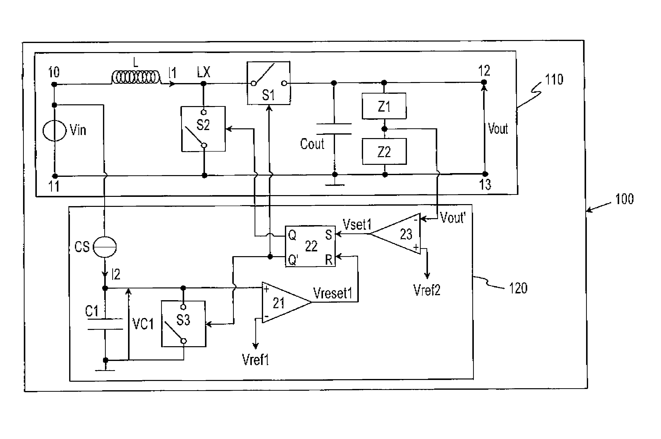
[0036]FIG. 1 is a schematic diagram of a DC to DC converter system 100 without zero current detection according to the present invention. The DC to DC converter system 100 comprises a synchronous up DC to DC converter 110 for converting an input voltage Vin (e.g. battery voltage) across the input terminals 10, 11 into a higher regulated output voltage Vout across the output terminals 12, 13, and a control circuit 120 for regulating the output voltage Vout through a switch mode.

[0037]Such DC to DC converter 110 also comprises switching devices S1, S2 driven by the control circuit 120 with an opposite switching sequence, which may be transistors (e.g. MOSFET, BJT) or any other controllable semiconductor switching devices, and an external inductor L for storing energy in the magnetic field generated by the current I1 that flows through it and avoiding to short-circuit the input voltage Vin when the switching device S2 is turned on.

[0038]The control circuit 120 contains a capacitor C1 a...

second embodiment

[0043]FIG. 2 depicts a schematic diagram of a DC to DC converter system 100 with zero current detection according to the present invention when in PFM mode. The DC to DC converter system 100 of FIG. 2 comprises the synchronous up DC to DC converter 110 of FIG. 1 and the control circuit 120 of FIG. 1 with the addition of a second set-reset flip flop 24, two AND gates 25, 26, and a third comparator 30 for detecting a zero current through the inductor L.

[0044]In this second embodiment, the DC to DC converter system 100 is now supposed to operate in PFM mode, such that the current I1 passing through the inductor L is supposed to have sufficient time in order to reach a zero value.

[0045]Like the first embodiment of FIG. 1, the set-reset flip flop 22 is reset after the voltage VC1 across the capacitor C1 increasingly reaches the reference voltage Vref1. Nevertheless, this second embodiment differs from the first one in that the comparison signal Vreset1 is not only sent towards the reset ...


PUM


Abstract

The present invention relates to a DC to DC converter system (100), which comprises converter means (110) and control means (120). The switching sequence of the first, second and third switching means (S1, S2, S3) is controlled by the control means (120) in such a manner that, during the on-time of the second switching device (S2), the first current (II) that flows through the inductive storage element (L) of the converter means (110) can be indirectly measured through the first voltage (VC1) across the capacitive storage element (C1), which is being charged with a second current (12) proportional to the input voltage (Vin) of the converter means (110) and provided by the current source (CS). Thus, the on-time of the second switching means (S2) varies inversely proportional to the input voltage (Vin).

Description

CROSS-REFERENCE TO RELATED APPLICATION(S)[0001]The present application claims priority under 35 U.S.C. §365 to International Patent Application No. PCT / EP2008 / 065238 filed Nov. 10, 2008, entitled “LOW POWER CONTROLLER FOR DC TO DC CONVERTERS”. International Patent Application No. PCT / EP2008 / 065238 claims priority under 35 U.S.C. §365 and / or 35 U.S.C. §119(a) to European Patent Application No. 07120341.8 filed Nov. 9, 2007 and which are incorporated herein by reference into the present disclosure as if fully set forth herein.FIELD OF THE INVENTION[0002]The present invention relates to a DC to DC converters, and more particularly to a low power controller for DC to DC converters exhibiting an on-time variable according to the input voltage of the DC to DC converters.BACKGROUND OF THE INVENTION[0003]Regulated or controlled power supplies are found in virtually all electronic devices, including for example battery chargers, cellular telephones, computers, computer monitors, televisions,...

Claims


Application Information

Patent Timeline
Patent Type & Authority Patents(United States)
IPC IPC(8): G05F1/40G05F1/613
CPCH02M3/1588Y02B70/1466Y02B70/10
Inventor BUTHKER, HENRICUS CORNELIS JOHANNES
Owner ST ERICSSON SA
Why Eureka
Try Eureka