
Optical scanning apparatus provided with resonance-driven swing mirror and image forming apparatus

an optical scanning apparatus and resonance-driven technology, applied in the direction of electrical apparatus, pictoral communication, etc., can solve the problems of more likely occurrence of errors, inability to directly solve inverse functions, and inconstant angular velocity, so as to reduce cost and track control the effect of error

Inactive Publication Date: 2013-10-01
CANON KK
View PDF8 Cites 3 Cited by
  • Summary
  • Abstract
  • Description
  • Claims
  • Application Information

AI Technical Summary

Benefits of technology

[0014]The present invention provides an optical scanning apparatus capable of suppressing cost and track control error due to an offset related to a center of swing of a resonant type optical deflection apparatus, and an image forming apparatus including such an optical scanning apparatus.

Problems solved by technology

The resonant type optical deflection apparatus based on a single resonance frequency has a problem in that the scanning angle of the mirror varies in a sine wave form in principle, resulting in a problem in that the angular velocity is not constant.
However, the sine function in the track equation is a non-linear function involving infinite orders and is a composite function thereof, and thus it is impossible to directly solve an inverse function.
Since the conversion matrix M−1 obtained by the above operation is a linear approximation, occurrence of an error is more likely as the distance from the expansion point increases.
That is, there is a problem that if track control is performed assuming that the offset amount is zero, an offset appears as a phase control error of the second harmonic.
In this manner, control error due to an offset error is conspicuously reflected, and a phase deviation of the second harmonic distorts the approximately-constant velocity track, and therefore, a scanning error due to the distortion occurs.
Because of the reason described above, there is a problem that even a small offset amount causes a phase deviation of the second harmonic, and results in a very conspicuous scanning error as shown in FIG. 11, such that the image is distorted.
Also, since the track deviates from the convergence point for the target track, a sufficient feedback gain cannot be applied, and jitter increases.

Method used


Image

  • Optical scanning apparatus provided with resonance-driven swing mirror and image forming apparatus
  • Optical scanning apparatus provided with resonance-driven swing mirror and image forming apparatus
  • Optical scanning apparatus provided with resonance-driven swing mirror and image forming apparatus

Examples


Embodiment Construction

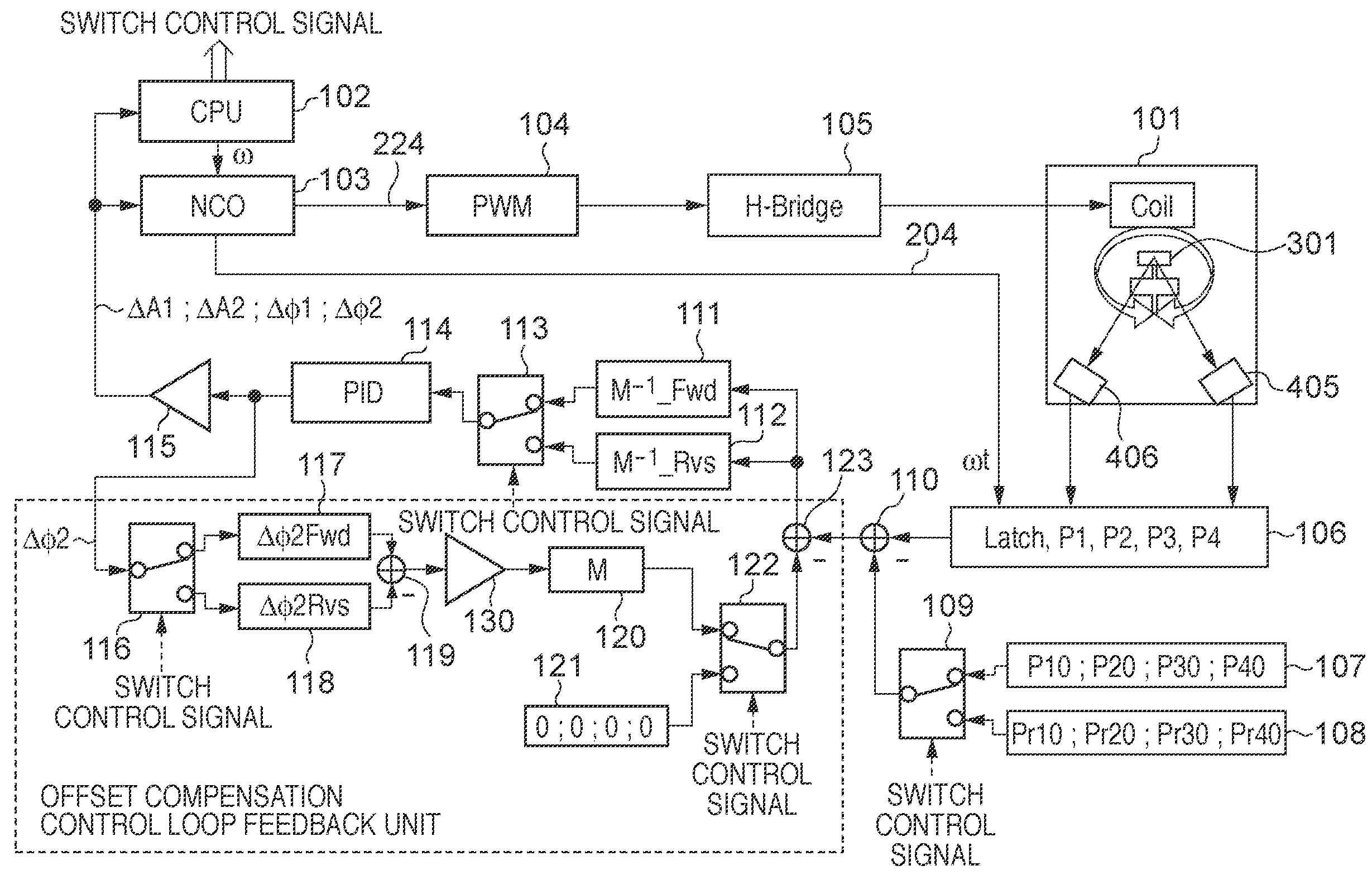
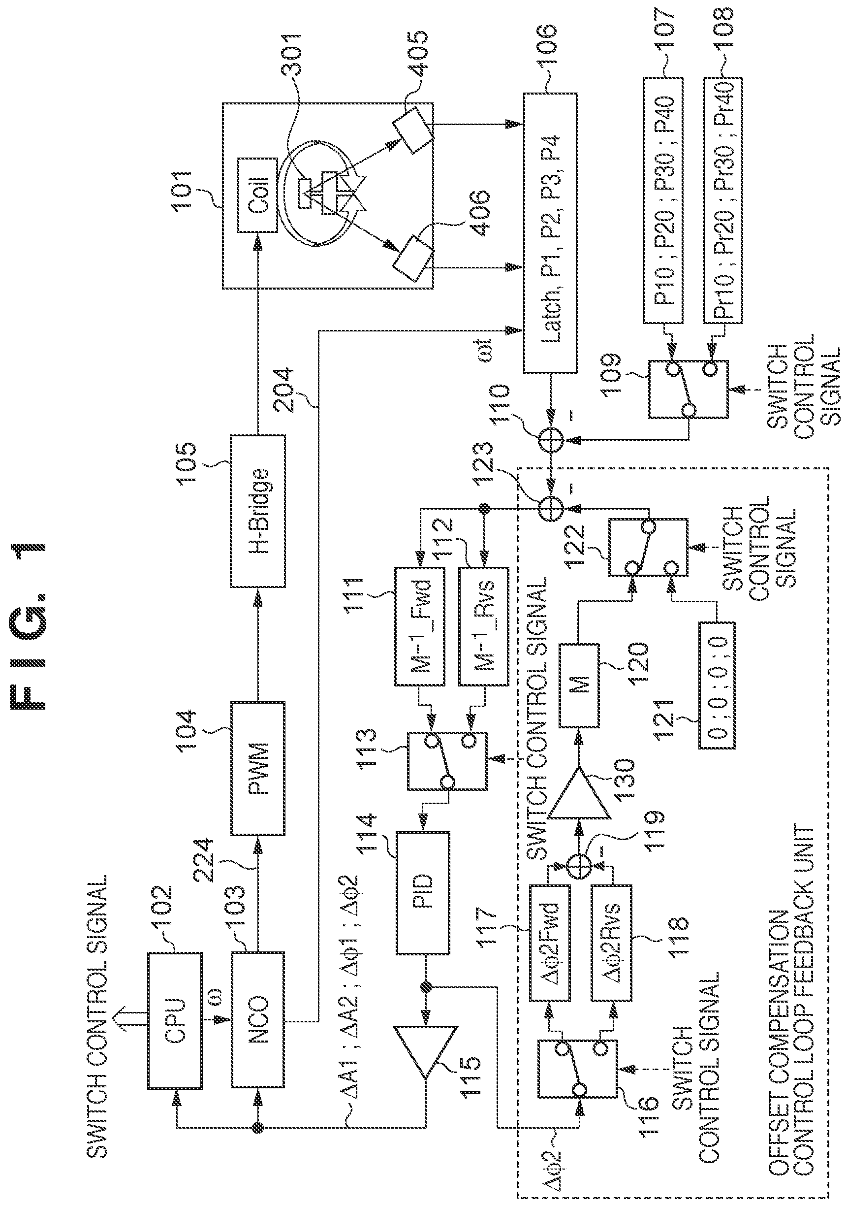
[0028]Hereinafter, a mechanism that realizes offset detection in which an offset value that causes an error in track control is read with a high accuracy without making any particular expensive innovation in an optical beam detection system. An extracted offset value is compensated with a high accuracy by a simple configuration. Specifically, track information that is lacking for extracting offset information from optical beam detection information with a matrix is supplemented by changing a drive parameter, thereby enabling extraction of such offset information. That is, a target track phase component is parameterized with respect to a phase component that has crosstalk with respect to an offset from the nature of the function of the track equation. Then, an offset value is calculated based on a phase difference component obtained from control results of two tracks. By this method, it is made possible to detect a phase component due to an offset caused by geometric characteristics ...


PUM


Abstract

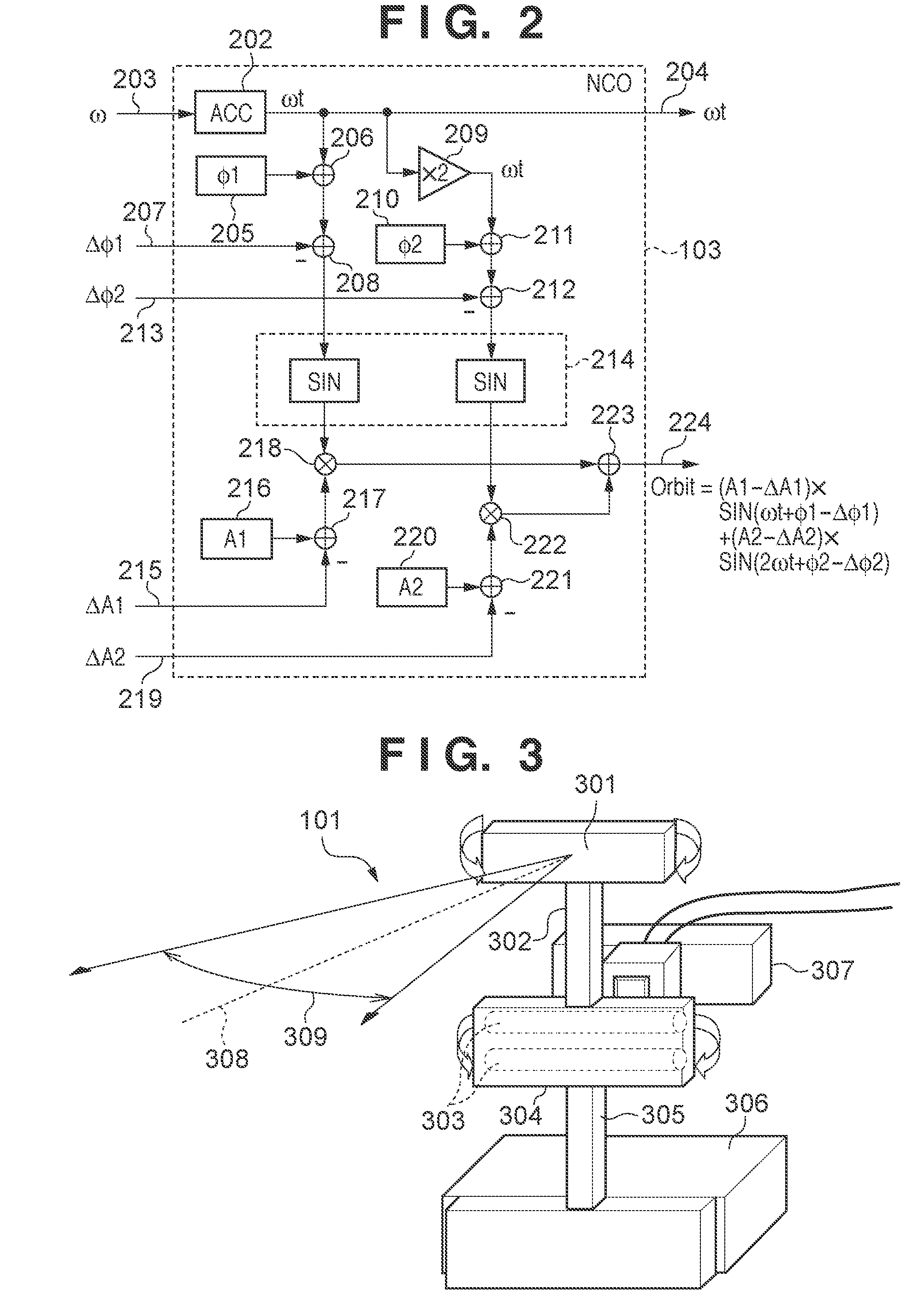
An optical scanning apparatus capable of suppressing a track error is provided. The apparatus includes a swing mirror supported by a torsional vibration system having a first natural frequency and a second natural frequency that is a double of the first natural frequency, and a driving unit applying a swing torque to the vibration system. The apparatus can detect passage of an optical beam at two locations and output track information of the swing mirror, and perform feedback control. When the feedback control is performed, the apparatus sequentially switches target tracks of scanning in a forward and a backward direction, the phases of the second natural frequency of the target tracks being mutually reversed, calculates an amount of offset compensation based on a difference between the predetermined target track and the track for each scanning in the forward and backward direction, and reflects the amount in the feedback control.

Description

BACKGROUND OF THE INVENTION[0001]1. Field of the Invention[0002]The present invention relates to a technique for high-accuracy driving of a swing oscillation element in an optical scanning apparatus and an image forming apparatus.[0003]2. Description of the Related Art[0004]Conventionally, various optical deflection apparatuses have been proposed where a mirror is resonance-driven. For example, Japanese Patent Laid-Open No. 2005-292627 discloses a resonant type optical deflection apparatus based on a single resonance frequency. The resonant type optical deflection apparatus based on a single resonance frequency has a problem in that the scanning angle of the mirror varies in a sine wave form in principle, resulting in a problem in that the angular velocity is not constant. In order to solve this, Japanese Patent Laid-Open No. 2005-326462 proposes a resonant type optical deflection apparatus based on an approximately-constant angular velocity. With the resonant type optical deflectio...

Claims


Application Information

Patent Timeline
Patent Type & Authority Patents(United States)
IPC IPC(8): H04N1/04
CPCH04N1/047H04N1/06H04N1/0635H04N2201/0471H04N2201/04713H04N2201/04729H04N2201/04732H04N2201/04744H04N2201/04755H04N2201/04793H04N2201/04796
Inventor MATSUO, SHIMPEI
Owner CANON KK
Learn More