
Enhanced visual feedback for touch-sensitive input device

a touch-sensitive input and enhanced technology, applied in the field of input mechanisms, can solve the problems of limited operation set, user difficulty in activating the correct command, and the operation in connection with the control of an electronic device is not particularly well suited to direct manipulation, so as to improve the visual feedback effect, improve the visual appearance, and improve the effect of visual feedback

Inactive Publication Date: 2013-10-01
QUALCOMM INC
View PDF33 Cites 12 Cited by
  • Summary
  • Abstract
  • Description
  • Claims
  • Application Information

AI Technical Summary

Benefits of technology

This solution enhances user experience by providing immediate and intuitive visual feedback, reducing user uncertainty and allowing for a wider range of commands to be accessible without occupying valuable screen space, while maintaining minimal complexity and learning curve.

Problems solved by technology

However, some operations in connection with control of an electronic device are not particularly well suited to direct manipulation.
In addition, providing on-screen buttons for such functions allows only a limited set of operations to be available at any given time, since there is often insufficient screen space to provide buttons for all such functions.
In some cases, on-screen buttons or objects are relatively small, causing some users to have difficulty activating the correct command or object, or even causing them to inadvertently cause the wrong command or object to be activated or manipulated.
This problem, which is particularly prevalent in devices having small screens, can cause touch-screens to be relatively unforgiving in their interpretation of user input.
In addition, as a natural consequence of combining an output device with an input device in the same physical space, the use of a touch-screen often causes users to obscure part of the screen in order to interact with it.
Screens layouts may be designed so that important elements tend not to be obscured; however, such design may not take into account right- or left-handedness.
Another disadvantage of touch-sensitive screens is that their dynamic nature makes it difficult for users to provide input without looking at the screen.
A user cannot normally discern the current state of the device without looking at it, and therefore cannot be sure as to the current location or state of various on-screen buttons and controls at any given time.
This makes it difficult to control the device while it is one's pocket, or while one is engaged in a task that inhibits one's ability to look at the device.
Touch-sensitive screens and pads often do not provide users with sufficient feedback to assure the user that the user's input has been recognized.
In particular, touch-sensitive pads often have no output mechanism to offer any visual feedback at the point of contact.
The lack of visual feedback can lead to uncertainty as to whether the user's input has been received or recognized.
In addition, conventional touch-sensitive screens and pads often do not provide a mechanism to distinguish between different types of tactile input.
For example, a touch on an on-screen object may signify the user's intention to select the object or to activate it; however, many conventional touch-sensitive screens provide no reliable mechanism for distinguishing between these two actions with respect to the on-screen object.
Double-clicking is known in conventional computer-based graphical user interfaces to signify an activation action in certain contexts; however, double-clicking is often perceived as cumbersome in a touch-based interface for a handheld device, and / or is often reserved for other use.
However, without adequate feedback a user may be unsure as to whether he or she has held the point of contact long enough to activate a tap-and-hold action rather than a tap action.

Method used


Image

  • Enhanced visual feedback for touch-sensitive input device
  • Enhanced visual feedback for touch-sensitive input device
  • Enhanced visual feedback for touch-sensitive input device

Examples


Embodiment Construction

Definitions

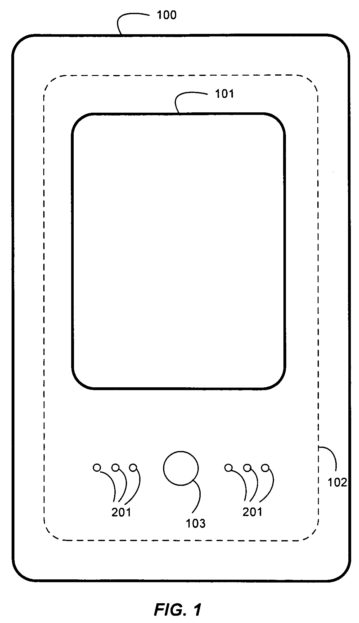
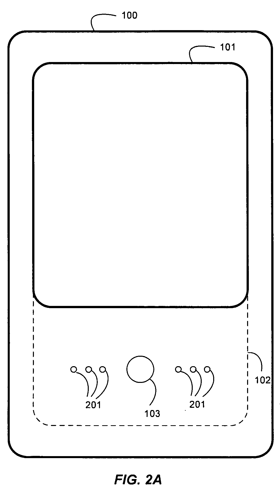
[0050]For purposes of the following description, the following terms are defined:[0051]Touch-sensitive surface: a surface of a device that is capable of detecting contact;[0052]Touch-sensitive screen: a touch-sensitive surface that also functions as a display screen;[0053]Touch command: any command that is entered by the user by touching a touch-sensitive surface;[0054]Direct manipulation: a touch command whose target is specified by contact with a element displayed on a touch-sensitive screen;[0055]Gesture: a touch command that includes a distinctive motion that can be interpreted to specify which command is to be performed;[0056]Gesture area (or touch-sensitive pad): a touch-sensitive surface that does not function as a display screen.

[0057]These terms are not intended to be limiting of the scope of the invention. For example, although the invention is described in the context of an embodiment wherein commands are detected by touching a surface, one skilled in the art w...


PUM


Abstract

A touch-sensitive input device provides improved visual feedback at (or near) the point and time of contact. As the user touches a touch-sensitive screen or pad, a portion of the screen or pad changes in visual appearance to indicate that the input has been received. In one embodiment, the change in visual appearance is localized to an area proximate to the point of contact. In one embodiment, the change in visual appearance is accomplished by illuminating an area proximate to and centered around the point of contact. In another embodiment, the change in visual appearance is accomplished by illuminating one or more illuminable elements, such as light-emitting diodes (LEDs) on the touch-sensitive pad.

Description

CROSS-REFERENCE TO RELATED APPLICATION[0001]The present application is related to U.S. patent application Ser. No. 12 / 115,992, filed May 6, 2008 for “Extended Touch-Sensitive Control Area for Electronic Device”, the disclosure of which is incorporated herein by reference.[0002]The present application is related to U.S. patent application Ser. No. 11 / 379,552, filed Apr. 20, 2006 for “Keypad and Sensor Combination to Provide Detection Region that Overlays Keys”, the disclosure of which is incorporated herein by reference.[0003]The present application is related to U.S. patent application Ser. No. 11 / 948,885, filed Nov. 30, 2007 for “Computing Device that Determines and Uses Applied Pressure from User Interaction with an Input Interface”, the disclosure of which is incorporated herein by reference.[0004]The present application is related to U.S. patent application Ser. No. 11 / 849,133, filed Aug. 31, 2007 for “Soft-User Interface Feature Provided in Combination with Pressable Display Su...

Claims


Application Information

Patent Timeline
Patent Type & Authority Patents(United States)
IPC IPC(8): G08B5/00G06F3/041
CPCG06F3/04886
Inventor DUARTE, MATIAS GONZALOSHIPLACOFF, DANIEL MARC GATANLYON, JEREMY GODFREYSKILLMAN, PETERDOMINGUEZ, DIANNE PARRYDELLINGER, RICHARD R.
Owner QUALCOMM INC
Learn More