Eureka AIR delivers breakthrough ideas for toughest innovation challenges, trusted by R&D personnel around the world.

Lift mechanism for added stability for a swim platform of a boat

a technology for lifting and lifting a swim platform and a boat, which is applied in the field of boats, can solve the problems of difficult or impossible for a user to manually deploy such watercraft, the weight of the watercraft greatly affects the center of gravity of the boat, and the difficulty or inability of the user to lift such heavy watercraft, etc., and achieves the effect of providing rigidity to the swim platform

Inactive Publication Date: 2013-09-24
NAUTICAL STRUCTURES IND
View PDF2 Cites 4 Cited by
  • Summary
  • Abstract
  • Description
  • Claims
  • Application Information

AI Technical Summary

Benefits of technology

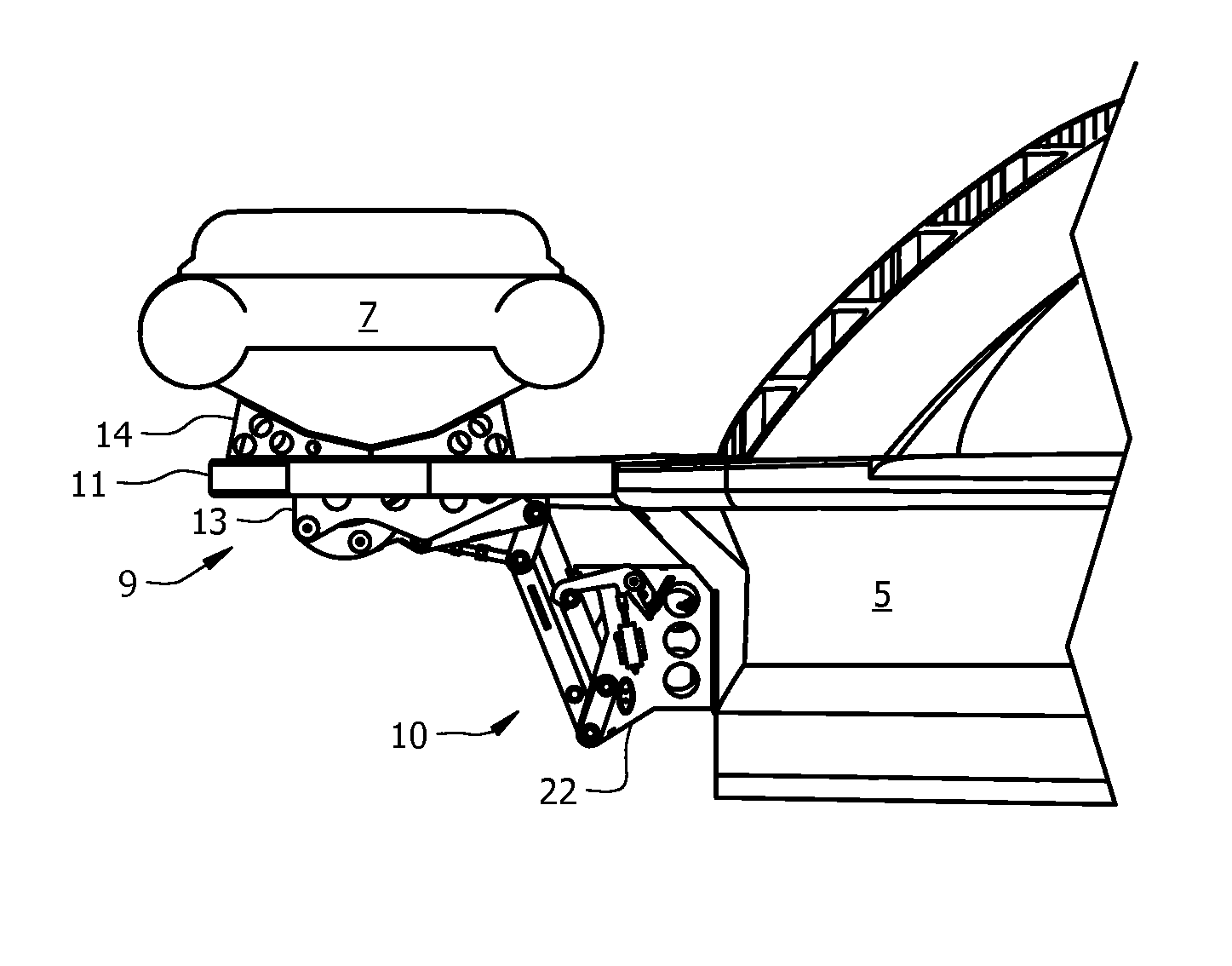
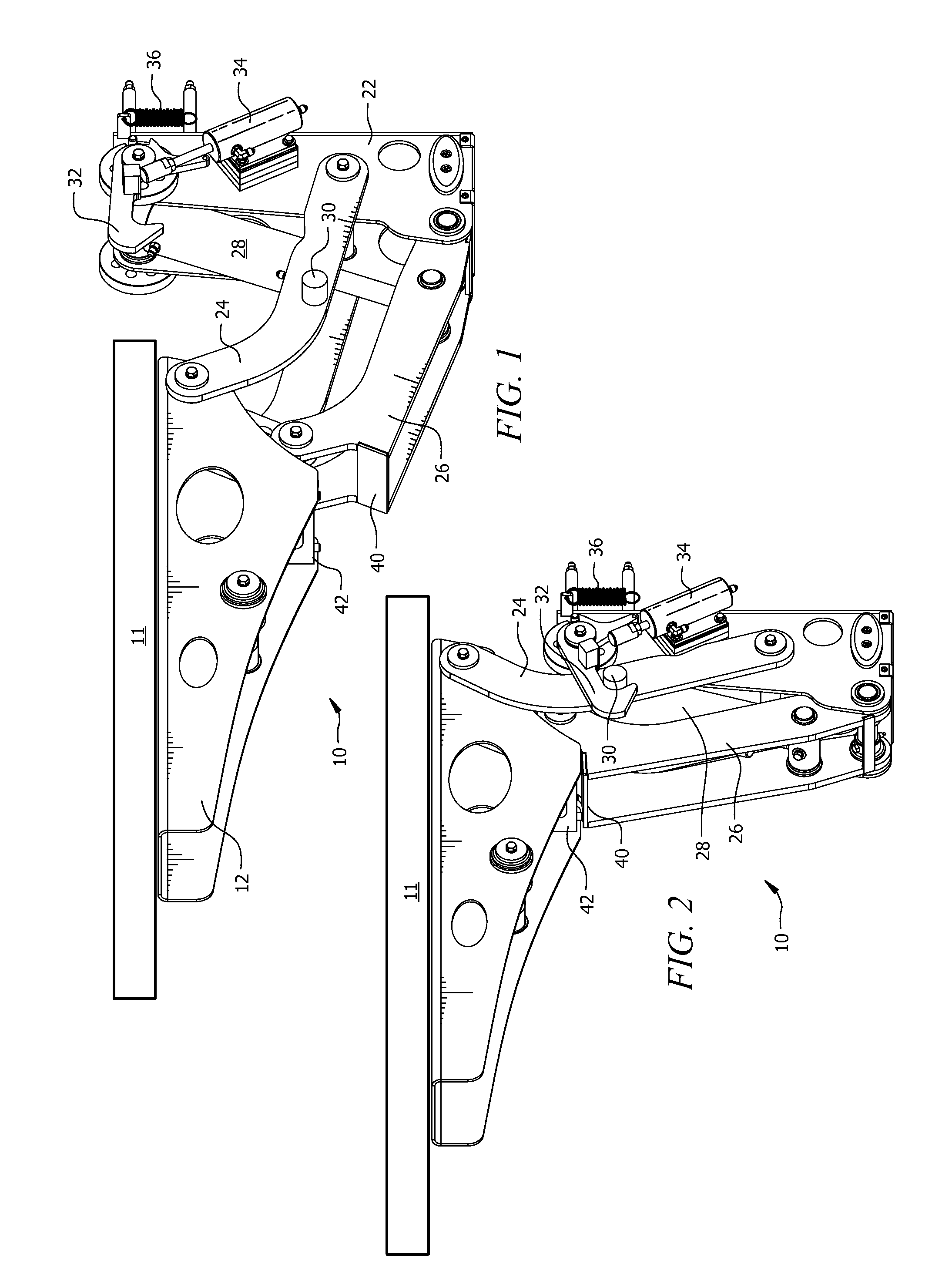
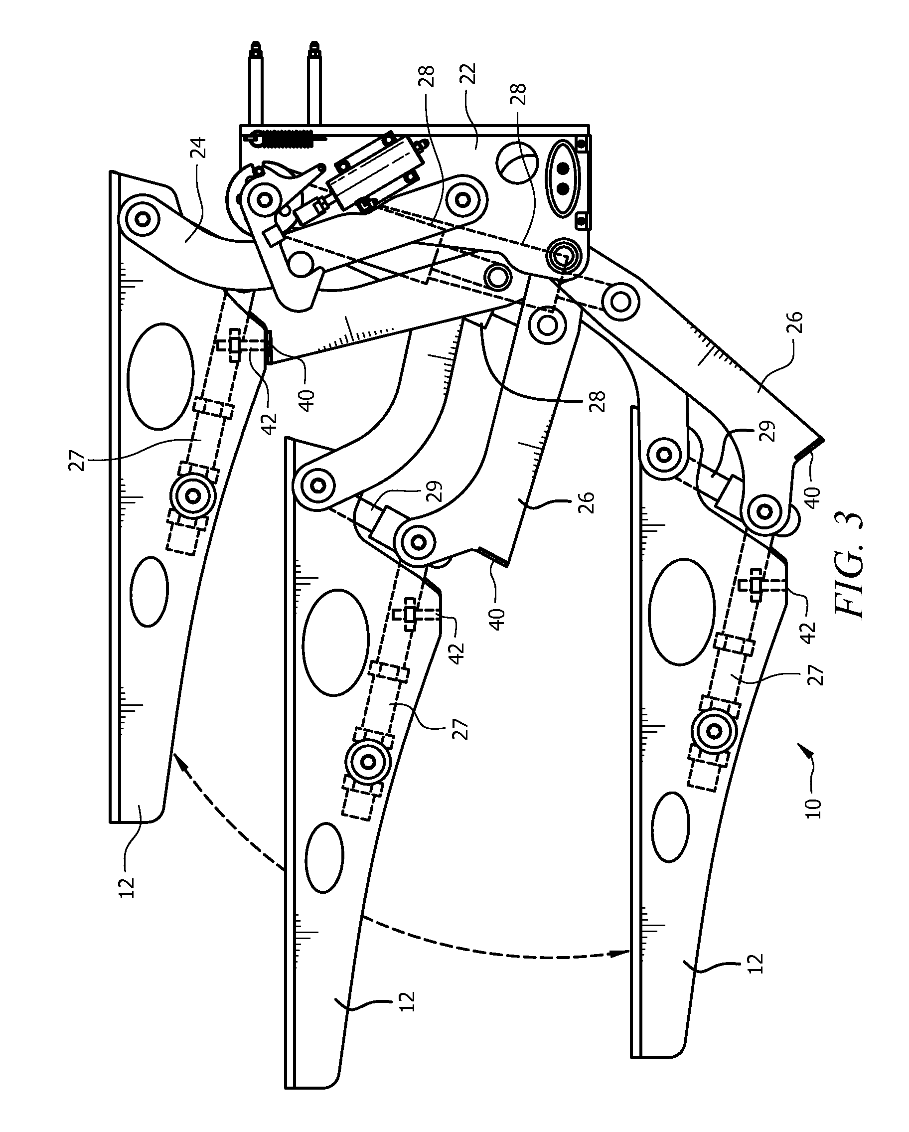
[0009]The swim platform lift mechanism mounts between the transom of a boat and a bottom surface of a swim platform, providing for lifting / lowering of the swim platform from a retracted position that is level with the deck of the boat to a deployed position where the swim platform is below the surface of the water surrounding the boat. In the deployed position, easy deployment of a dingy or other watercraft that is stored on the swim platform is made possible. The swim platform lift mechanism has an adjustable stop and a rest area that provides a third support lever to stiffen the swim platform when the swim platform is in the retracted position, reducing up / down movement and oscillation.
[0012]In another embodiment, a method of lifting a swim platform for a boat is disclosed. The boat is floating in a liquid. The method includes connecting the swim platform to a transom of the boat with a deployment lift mechanism. The deployment lift mechanism includes a transom bracket affixed to the transom of the boat and a platform bracket affixed to the swim platform. The deployment lift mechanism has upper arms hingedly interfaced at one end to an upper area of the transom bracket and at a distal end to the platform bracket and lower arms hingedly interfaced at one end to a lower area of the transom bracket and at a distal end to the platform bracket. The deployment lift mechanism has a hydraulic ram interfaced between an upper area of the transom bracket and the lower arms. A stop is positioned on a lower surface of the platform bracket and rest areas is positioned at the distal end of the lower arms whereas the stop engages with the rest areas in the first position, thereby providing structural support to the platform bracket. The method continues with lowering the swim platform using the deployment lift mechanism until the swim platform is below a surface of the liquid, positioning a water craft upon the swim platform and raising the swim platform using the deployment lift mechanism until the swim platform is substantially level with a deck of the boat, whereas the rest areas are supported by the stop, thereby providing rigidity to the swim platform.

Problems solved by technology

This helps keep swimmers and divers away from the features, such as propellers, that sometimes come into contact with the swimmer / diver, causing injuries.
With such heavier watercraft, it is difficult or impossible for a user to manually deploy such watercraft and even harder to lift these heavy watercraft back onto the swim platform.
There are several problems with prior swim platforms that have mechanical systems to lower the watercraft (dingy, jet ski, etc.) into the water.
First, the weight of the mechanical systems for lowering, the weight of the swim platform itself, and the weight of the watercraft greatly affect the center of gravity of the boat.
This additional weight is especially disadvantageous for many boats that must get up “on plane” during cruising speeds, requiring more fuel and time to get on plane, and increasing the speed required to remain on plane.
This results in a vast reduction in fuel economy.
It is very disconcerting for a boater to step on a swim platform that bends or oscillates up and down.
Swim platforms that have mechanical systems to lower the watercraft often do not have this stiff, sturdy feel.
When one steps onto a mechanically lowered / raised swim platform of the prior art, the swim platform bends or bounces, yielding an uneasy feeling.
Most conventional lifts leave their arms in a position where they perform as bending beams and are therefore susceptible to noticeable deflection.

Method used


Image

  • Lift mechanism for added stability for a swim platform of a boat
  • Lift mechanism for added stability for a swim platform of a boat
  • Lift mechanism for added stability for a swim platform of a boat

Examples


Embodiment Construction

[0024]Reference will now be made in detail to the presently preferred embodiments of the invention, examples of which are illustrated in the accompanying drawings. Throughout the following detailed description, the same reference numerals refer to the same elements in all figures. Throughout this description, the term “boat” refers to any aquatic vehicle of any size or type including, but not limited to, boats, yachts, pleasure craft, etc. The term “dingy” refers to any secondary aquatic vehicle that is carried or towed by the boat including, but not limited to, jet skis, kayaks, canoes, a dingy, rafts, pontoon boats, etc. Throughout this description, the term “retracted position” refers to a condition in which the swim platform is substantially level with a deck of the boat and “deployed position” refers to a condition in which the swim platform is at a level lower than the deck of the boat, preferably below the surface of a body of water in which the boat is floating.

[0025]Referri...


PUM


Abstract

A swim platform lift mechanism is disclosed, the mechanism mounted between the transom of a boat and a bottom surface of a swim platform. The lift mechanism provides a powered lifting / lowering of the swim platform from a retracted position that is level with the deck of the boat to a deployed position in which the swim platform is below the surface of the water surrounding the boat and from the retracted position to an up-and-over position in which the swim platform and its contents are positioned above and forward of the rear edge of the deck. When in the retracted position, an adjustable stop interfaced to the swim platform abuts rest areas on lower arms of the lift mechanism, thereby providing structural support to the swim platform.

Description

FIELD[0001]This invention relates to boats and more particularly to a lift mechanism for lifting a swim platform of a boat.BACKGROUND[0002]Some boats have what is known as a swim platform extending outwardly from the rear of the boat (stern). For many uses, the swim platform is stationary and provides added space and safety features. The added space is very useful when swimming from the back of the boat, providing a clear area for the swimmer to board the boat when finished swimming. For inboard / outboard boats, the swim platform provides additional safety by extending outward, over the propeller and the outdrive. This helps keep swimmers and divers away from the features, such as propellers, that sometimes come into contact with the swimmer / diver, causing injuries.[0003]Another popular use for the swim platform is for transportation of a personal watercraft such as a dingy. For some light weight personal watercraft, such as canoes and kayaks, it is relatively easy for the user to sl...

Claims


Application Information

Patent Timeline
Patent Type & Authority Patents(United States)
IPC IPC(8): B63B35/40B63B23/02
CPCB63B27/143B63B2029/022
Inventor BOLLINE, ROBERTASSEFF, NICHOLASINGERSOLL, SUNTHORN
Owner NAUTICAL STRUCTURES IND
Why Eureka
Eureka Blog
Learn More