
System and method for wideband interference suppression

a wideband interference and suppression system technology, applied in the field can solve the problems of only being able to filter low frequency operations, affecting the efficiency of wideband interference suppression, and overflowing of adjacent communication channels into desired communication channels, etc., to achieve the effect of suppressing signal interference, simplifying the system and interference suppression control architecture, and minimal mitigating effects

Active Publication Date: 2013-09-03
LOCKHEED MARTIN CORP
View PDF15 Cites 4 Cited by
  • Summary
  • Abstract
  • Description
  • Claims
  • Application Information

AI Technical Summary

Benefits of technology

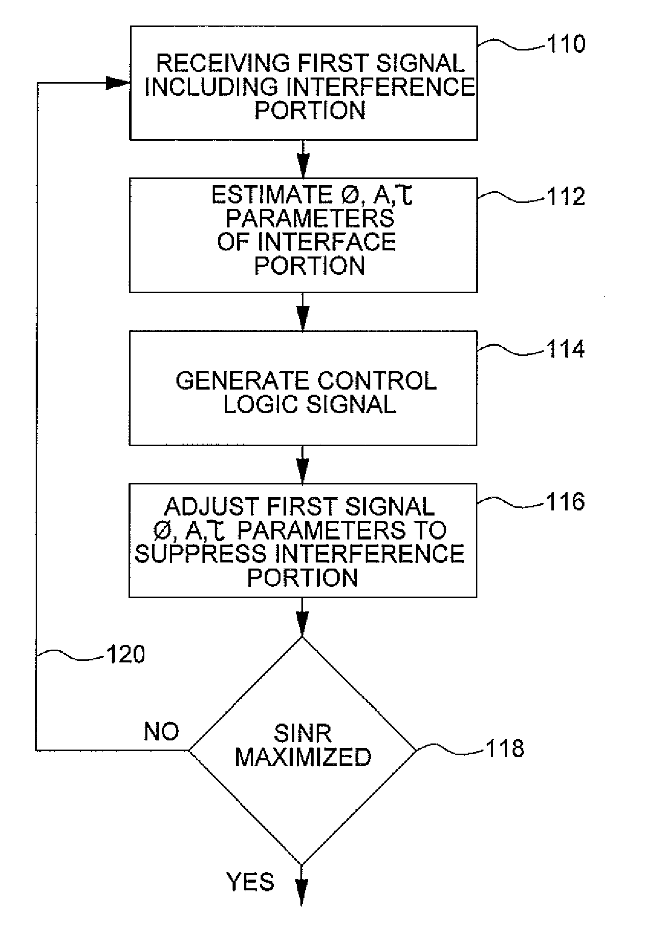
The present invention is a device that reduces signal interference in a wideband communication channel, while keeping the device simple and compact. It does not require the use of band-pass filters and can be used for all frequency ranges. The device has independent control over time delay, phase delay, and amplitude control, making it easier to control and suppress interference. The invention can be implemented as radio frequency integrated circuits with minimal size and power requirements, which lowers cost and makes the device more portable.

Problems solved by technology

In some instances, the interfering signal unintentionally results from adjacent communication channels overflowing into the desired communication channel.
Additionally, the usable radio spectrum is highly populated, and occupied communication channels can potentially act as interferers within a desired wideband communication channel.
In general, such filtering methods are only feasible for low frequency operations, and are limited by the low quality factors of integrated inductors and capacitors used to create the filtering.
Recently, the digital signal processing has become increasingly complex.

Method used


Image

  • System and method for wideband interference suppression
  • System and method for wideband interference suppression
  • System and method for wideband interference suppression

Examples


Embodiment Construction

[0020]The following detailed description and appended drawings describe and illustrate various embodiments of the invention. The description and drawings serve to enable one skilled in the art to make and use the invention, and are not intended to limit the scope of the invention in any manner. In respect of the methods disclosed, the steps presented are exemplary in nature, and thus, the order of the steps is not necessary or critical.

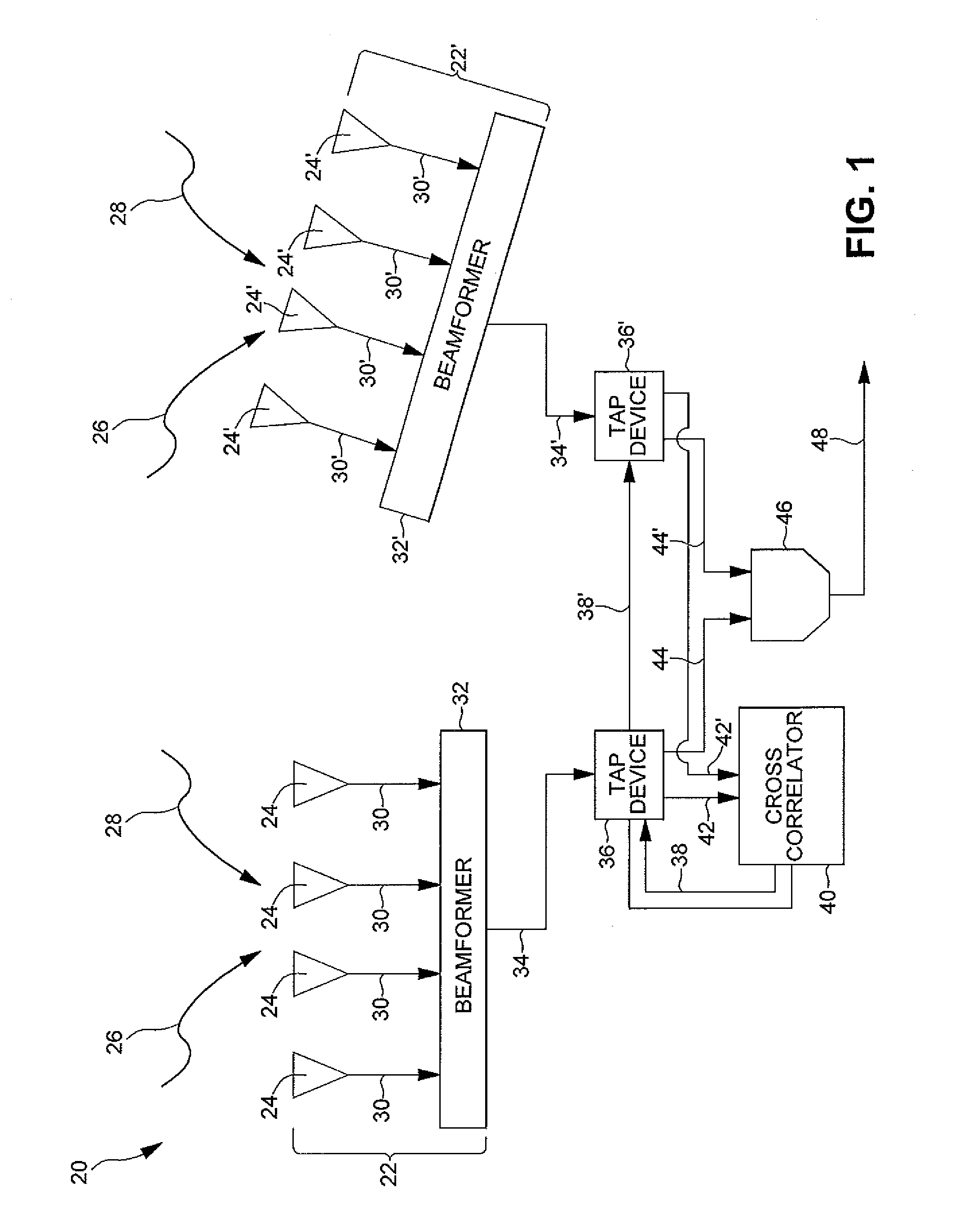
[0021]FIG. 1 illustrates a wideband interference suppression system 20 wherein a first antenna array 22 including multiple antenna elements 24 receives a wideband signal that includes a signal of interest portion 26 and an interference signal portion 28 combined together as a plurality of received signals 30. A beamformer 32 combines the received signals 30 into a coherent signal 34 that is received by a signal conditioning device 36, which provides selective, independent, and variable control over a time delay, an amplitude, a phase delay, RF signal ...


PUM


Abstract

A wideband interference suppression system comprises at least one signal conditioning device receiving at least one input signal having a signal of interest portion and an interference signal portion, wherein the at least one signal conditioning device is adapted to provide selective, independent, and variable control of one of a phase, a time delay, an amplitude, a radio frequency signal division, and a radio frequency signal summation of the at least one input signal to produce a modified signal. A tunable cross correlator receives a signal representative of the modified signal and is adapted to estimate one of an amplitude, a time delay and a phase delay parameter of the interference signal portion and to generate a control logic signal therefrom, wherein the control logic signal is received by the at least one signal conditioning device for independently and selectively activating and adjusting the various components thereof to suppress the interference signal portion.

Description

STATEMENT REGARDING FEDERALLY SPONSORED RESEARCH OR DEVELOPMENT[0001]Not applicable.CROSS-REFERENCE TO RELATED APPLICATIONS[0002]The present application claims priority to the following: U.S. Provisional Application Ser. No. 61 / 161,382 filed Mar. 18, 2009; U.S. Provisional Application Ser. No. 61 / 162,226 filed Mar. 20, 2009; U.S. Provisional Application Ser. No. 61 / 162,994 filed Mar. 24, 2009; and U.S. Provisional Application Ser. No. 61 / 180,410 filed May 21, 2009. Each of the foregoing Applications is incorporated by reference herein in its entirety.FIELD OF THE INVENTION[0003]The invention relates to interference suppression. In particular, this invention relates to a system and method to provide a time delay, a phase delay and an amplitude based cancellation circuit to suppress wideband interference.BACKGROUND OF THE INVENTION[0004]Radio frequency (“RF”) signal receivers must distinguish between a primary or desired signal and any interfering signal. In some instances, the interf...

Claims


Application Information

Patent Timeline
Patent Type & Authority Patents(United States)
IPC IPC(8): H04B1/10
CPCH04B7/0857
Inventor LAM, LAWRENCE K.SAIZ, NICHOLAS D.
Owner LOCKHEED MARTIN CORP
Learn More