Light-emitting diode (LED) driving circuit
a technology of led driving circuit and led diodes, which is applied in the direction of static indicating devices, instruments, semiconductor lamp usage, etc., can solve the problems of complicated led driving circuits and high design and manufacturing costs, and achieve the effect of simple driving structure and reduced components
- Summary
- Abstract
- Description
- Claims
- Application Information
AI Technical Summary
Benefits of technology
Problems solved by technology
Method used
Image

Examples
first embodiment
[0022]FIG. 4 is a schematic diagram illustrating the LED driving circuit 4 shown in FIG. 3. Referring to FIG. 4, an LED driving circuit 4 includes a first current mirror 41, a second current mirror 42 and a control circuit 43. The first current mirror 41 includes a plurality of first transistors Q11-Q1m. Each first transistor Q1i has a first terminal, a second terminal and a control terminal, where i is an integer from 1 to m. The first terminal of each first transistor Q1i is coupled to the second terminal of a corresponding first lightbar LB1i. The second terminals of the first transistors Q11-Q1m are coupled to one another and to the control circuit 43. The control terminals of the first transistors Q11-Q1m are coupled to one another and to the first terminal of one of the first transistors Q11-Q1m (e.g. Q11). The second current mirror 42 includes a plurality of second transistors Q21-Q2m. Each second transistor Q2i has a first terminal, a second terminal and a control terminals ...
second embodiment
[0029]FIG. 6 is a schematic diagram illustrating the LED driving circuit shown in FIG. 3. Referring to FIG. 6, an LED driving circuit 6 includes a first current mirror 61, a second current mirror 62 and a control circuit 63. The first current mirror 61 includes a first constant current source CS1, a plurality of first transistors Q11-Q1m and a second transistor Q2. The first constant current source CS1 provides a first constant current I1. Each of the first transistors Q11-Q1m and the second transistor Q2 has a first terminal, a second terminal and a control terminals terminal. The first terminal of each first transistor Q1i is coupled to the second terminal of a corresponding first lightbar LB1i. The second terminals of the first transistors Q11-Q1m and the second transistor Q2 are coupled to one another and to ground. The control terminals of the first transistors Q11-Q1m and the second transistor Q2 are coupled to one another and to the first terminal of the second transistor Q2,...
third embodiment
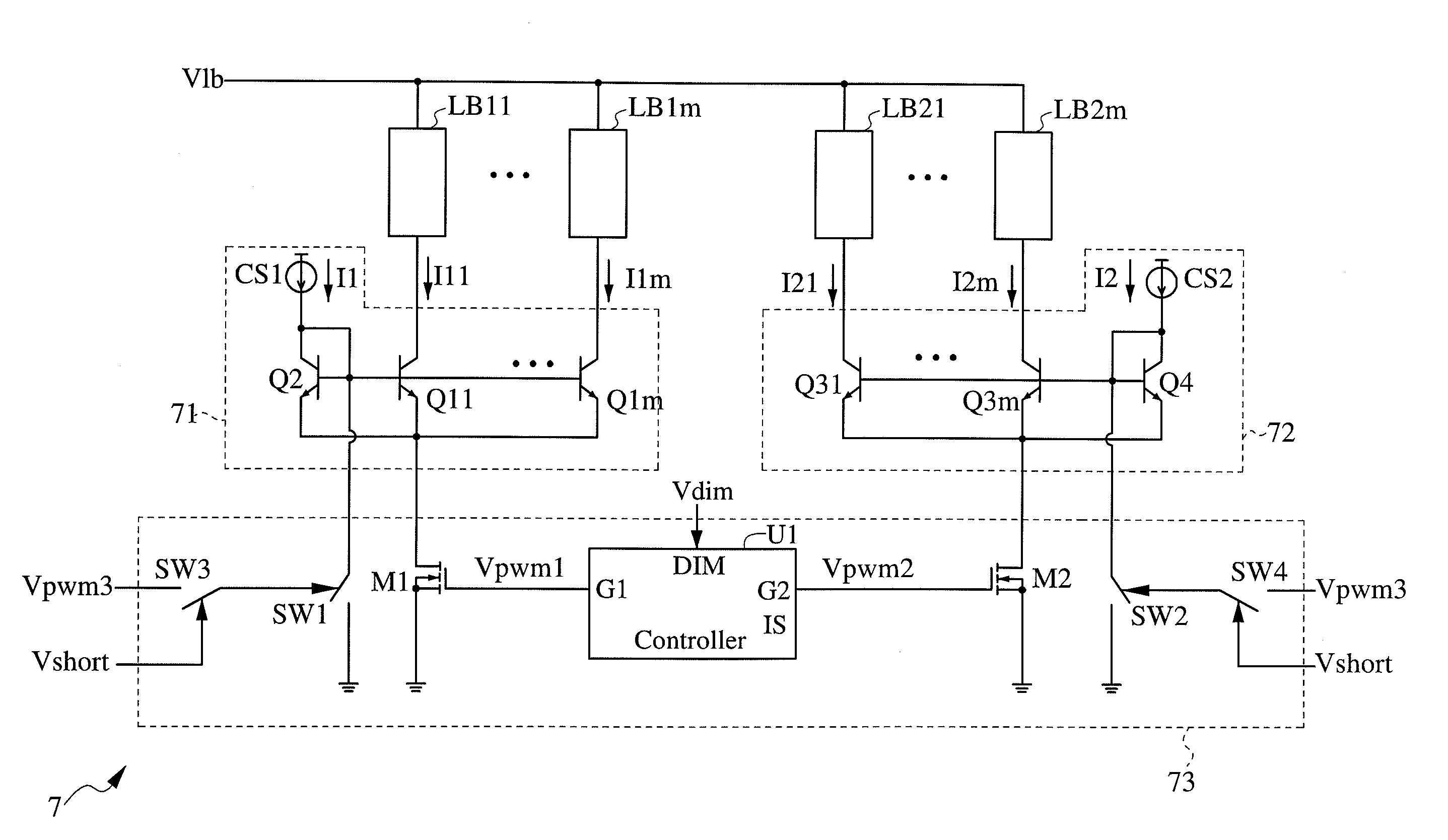
[0032]FIG. 7 is a schematic diagram illustrating the LED driving circuit shown in FIG. 3. Referring to FIG. 7, an LED driving circuit 7 includes a first current mirror 71, a second current mirror 72 and a control circuit 73. The first current mirror 71 includes a first constant current source CS1, a plurality of first transistors Q11-Q1m and a second transistor Q2. The first constant current source CS1 provides a first constant current I1. Each of the first transistors Q11-Q1m and the second transistor Q2 has a first terminal, a second terminal and a control terminal. The first terminal of each first transistor Q1i is coupled to the second terminal of a corresponding first lightbar LB1i. The second terminals of the first transistors Q11-Q1m and the second transistor Q2 are coupled to one another and to the control circuit 73. The control terminals of the first transistors Q11-Q1m and the second transistor Q2 are coupled to one another and to the first terminal of the second transist...
PUM
 Abstract
Description
Claims
Application Information
 - R&D
- Intellectual Property
- Life Sciences
- Materials
- Tech Scout
- Unparalleled Data Quality
- Higher Quality Content
- 60% Fewer Hallucinations
Browse by: Latest US Patents, China's latest patents, Technical Efficacy Thesaurus, Application Domain, Technology Topic, Popular Technical Reports.
© 2025 PatSnap. All rights reserved.Legal|Privacy policy|Modern Slavery Act Transparency Statement|Sitemap|About US| Contact US: help@patsnap.com