Variable power lens
a variable power and lens technology, applied in the field of variable power lenses, can solve the problems of difficult to provide variable power lenses therein, and achieve the effects of low price, simplified focus ring couplers, and high precision
- Summary
- Abstract
- Description
- Claims
- Application Information
AI Technical Summary
Benefits of technology
Problems solved by technology
Method used
Image
Examples
first embodiment
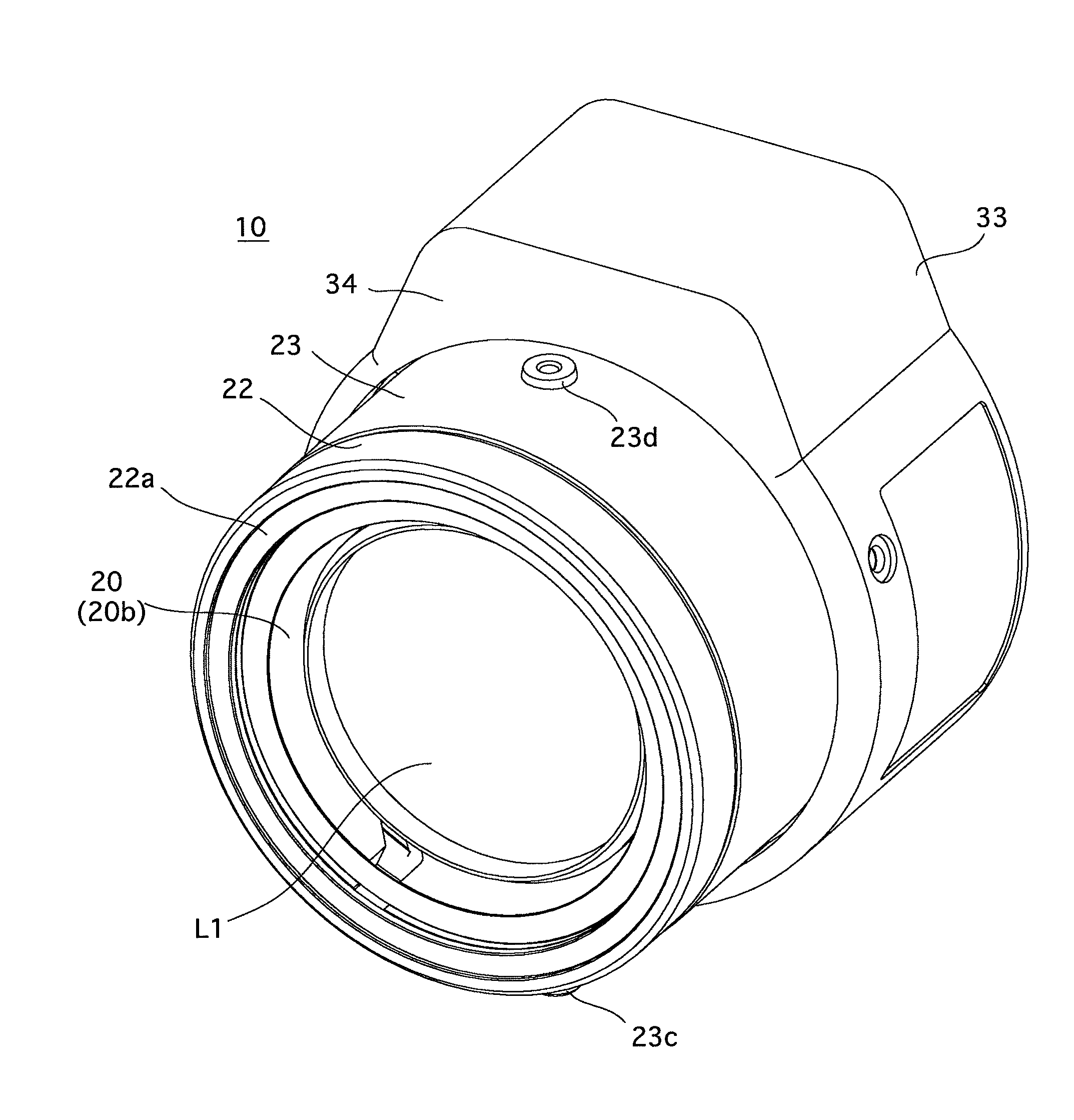
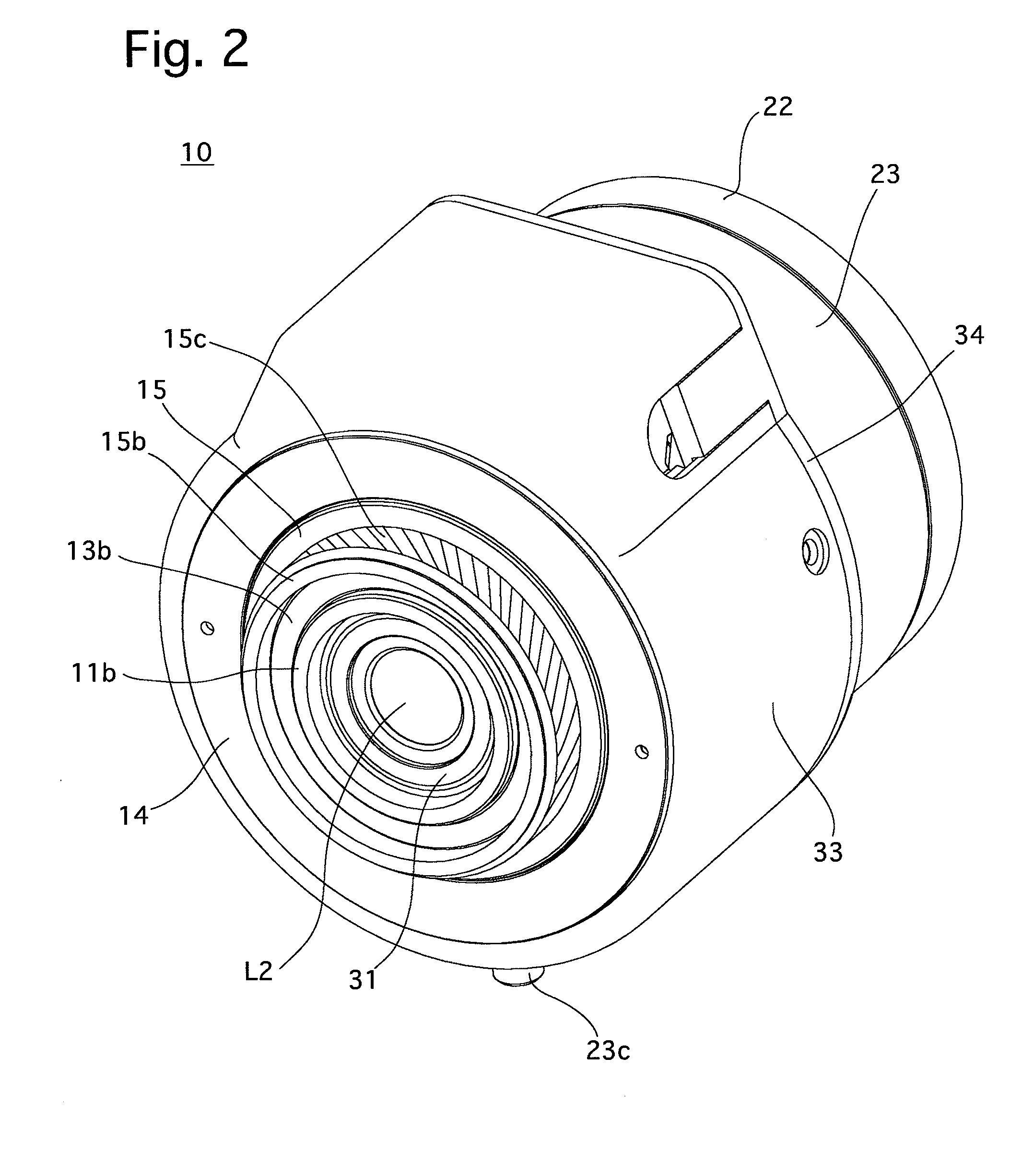
[0082]A focus ring coupler including the annular front-end flange 20b, the radially inner flange 22a, the front-end flange 23b and the front-cam-ring biasing spring 25, together with the focusing helicoid 24 constitute a focusing operation mechanism of the drive-ring movement controller according to the
[0083]As shown in FIGS. 3, 12A, 12B, 17 and 18, the focus ring 23 is provided, on an outer peripheral surface thereof at substantially radially symmetrical positions, with a lever support seat 23c and a screw support seat 23d, respectively, each of which has a screw hole formed therethrough in a radial direction. The variable power lens 10 is provided with a focus lever (an element of the focus operating member) PF (see FIGS. 3 and 17), the threaded base end of which is screwed into the lever support seat 23c to be supported thereby so as to project radially outwards from the focus ring 23. A limit screw 27 is screwed into the screw support seat 23d to be supported thereby. The thread...
second embodiment
[0105]A focus ring coupler including the front-end flange 20b′, the lug-guide space 20f, the retaining flange 23e, the lug-guide space 23f, the radially inner flange 23g and the lug insertion / removable holes 23h, together with the focusing helicoid 24 constitute a focusing operation mechanism of the drive-ring movement controller according to the
[0106]FIG. 35 shows the angular position between the front cam ring 20′ and the focus ring 23′ at which the front cam ring 20′ and the focus ring 23′ can be attached to and detached from each other. The three retaining lugs 20f that are formed on the front cam ring 20′ are positioned to correspond to the three lug insertion / removable holes 23h of the focus ring 23′ and can all be inserted into and removed from the lug-guide space 23f through the associated three lug insertion / removable holes 23h, respectively. The two positions of the limit screw 27 shown by two-dot chain lines in FIG. 35 show the range of rotation of the focus ring 23′ (app...
PUM
 Abstract
Description
Claims
Application Information
 - R&D
- Intellectual Property
- Life Sciences
- Materials
- Tech Scout
- Unparalleled Data Quality
- Higher Quality Content
- 60% Fewer Hallucinations
Browse by: Latest US Patents, China's latest patents, Technical Efficacy Thesaurus, Application Domain, Technology Topic, Popular Technical Reports.
© 2025 PatSnap. All rights reserved.Legal|Privacy policy|Modern Slavery Act Transparency Statement|Sitemap|About US| Contact US: help@patsnap.com


