
Vehicle door handle apparatus

a technology for a door handle and a handle, which is applied in the direction of wing knobs, lighting support devices, lock applications, etc., can solve the problems of complex lighting device manufacturing process, inability to prevent washing water and the like, and complex lighting device structure, etc., and achieves the effect of simple structur

Inactive Publication Date: 2013-09-03
ALPHA
View PDF14 Cites 8 Cited by
  • Summary
  • Abstract
  • Description
  • Claims
  • Application Information

AI Technical Summary

Benefits of technology

The present invention aims to provide a vehicle door handle apparatus that can illuminate the foot using a simple structure. The apparatus includes a front cover and a back cover that are coupled together to form the handle. The front cover has an irradiation opening and a harness insertion groove through which wire harnesses are inserted. The back cover closing the harness insertion groove securely fixes a lighting device in position. The lighting device can be easily attached without the need for screws or other fasteners, reducing rattle and noise during vehicle operation. The lens portion is designed to reduce scratches and maintain its lighting effect for a long time. The lens portion is made of translucent resin with a light diffusing agent, allowing the irradiation opening to illuminate a wide area around the foot.

Problems solved by technology

However, in the above-mentioned conventional example, since the operation handle is used while being exposed to the outside, there is a disadvantage that an occurrence of a short circuit and the like owing to entrance of rainwater, wash water and the like cannot be prevented if such a lighting device as an LED is only attached onto the operation handle.
Therefore, a joint portion between the case and the diffusing member that closes the opening of the case is provided, and accordingly, a structure of the lighting device is complicated.
Moreover, two-color molding or a joining step of the diffusing member is required, and so on, and accordingly, a manufacturing process of the lighting device becomes complicated.

Method used


Image

  • Vehicle door handle apparatus
  • Vehicle door handle apparatus
  • Vehicle door handle apparatus

Examples


Embodiment Construction

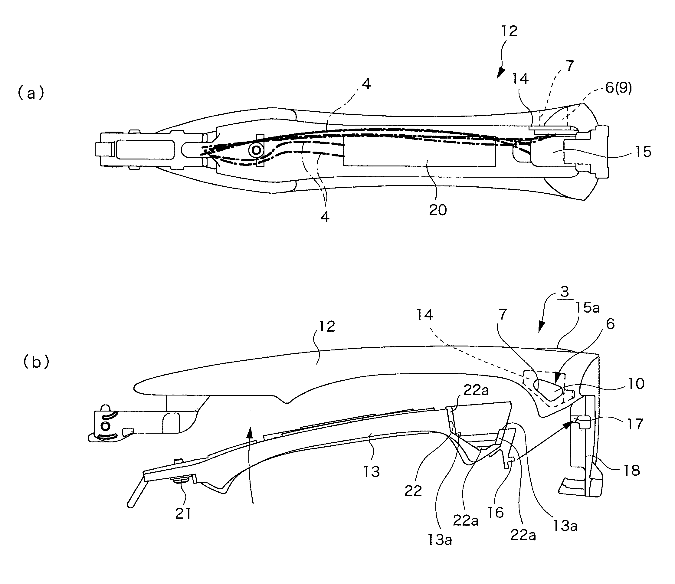
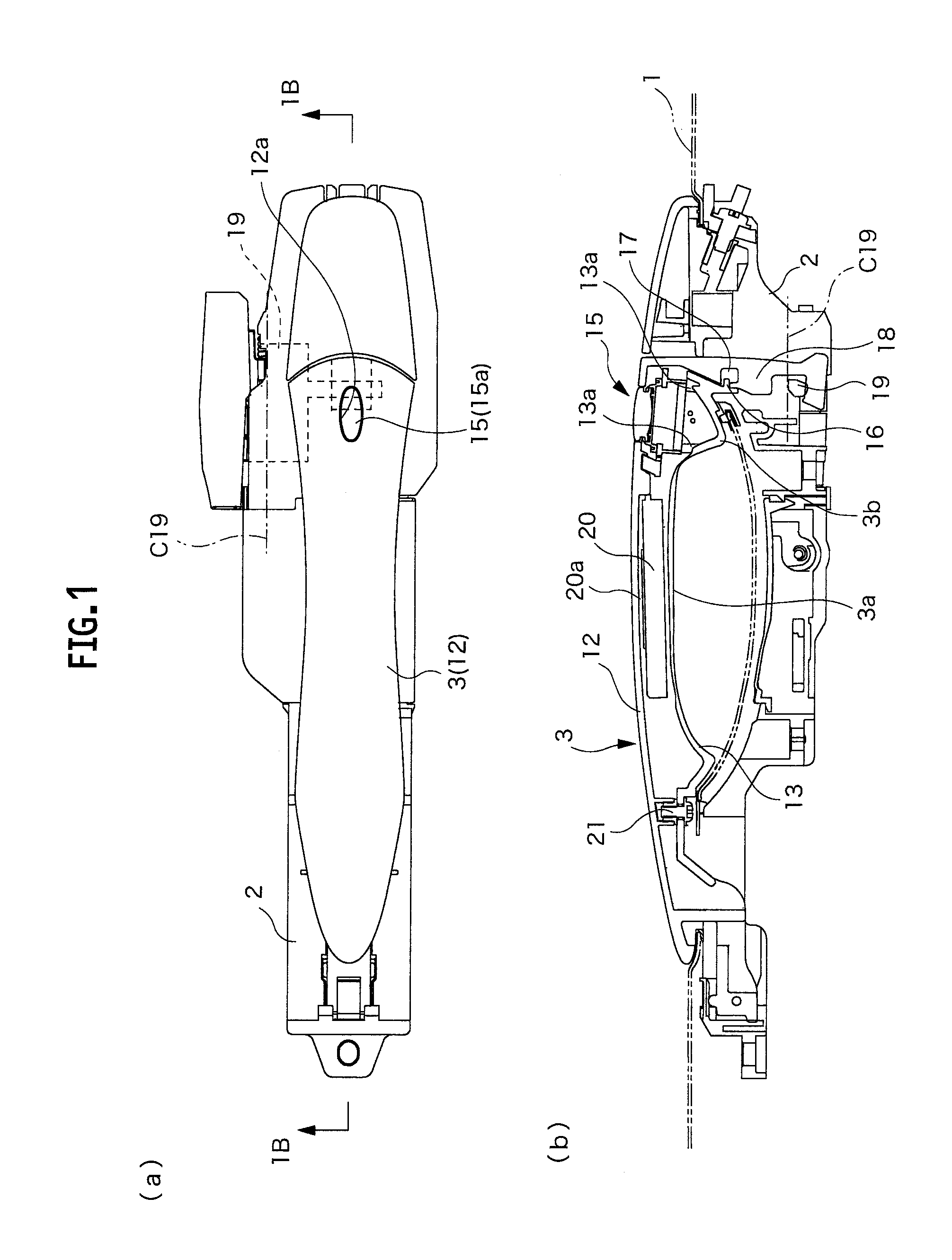
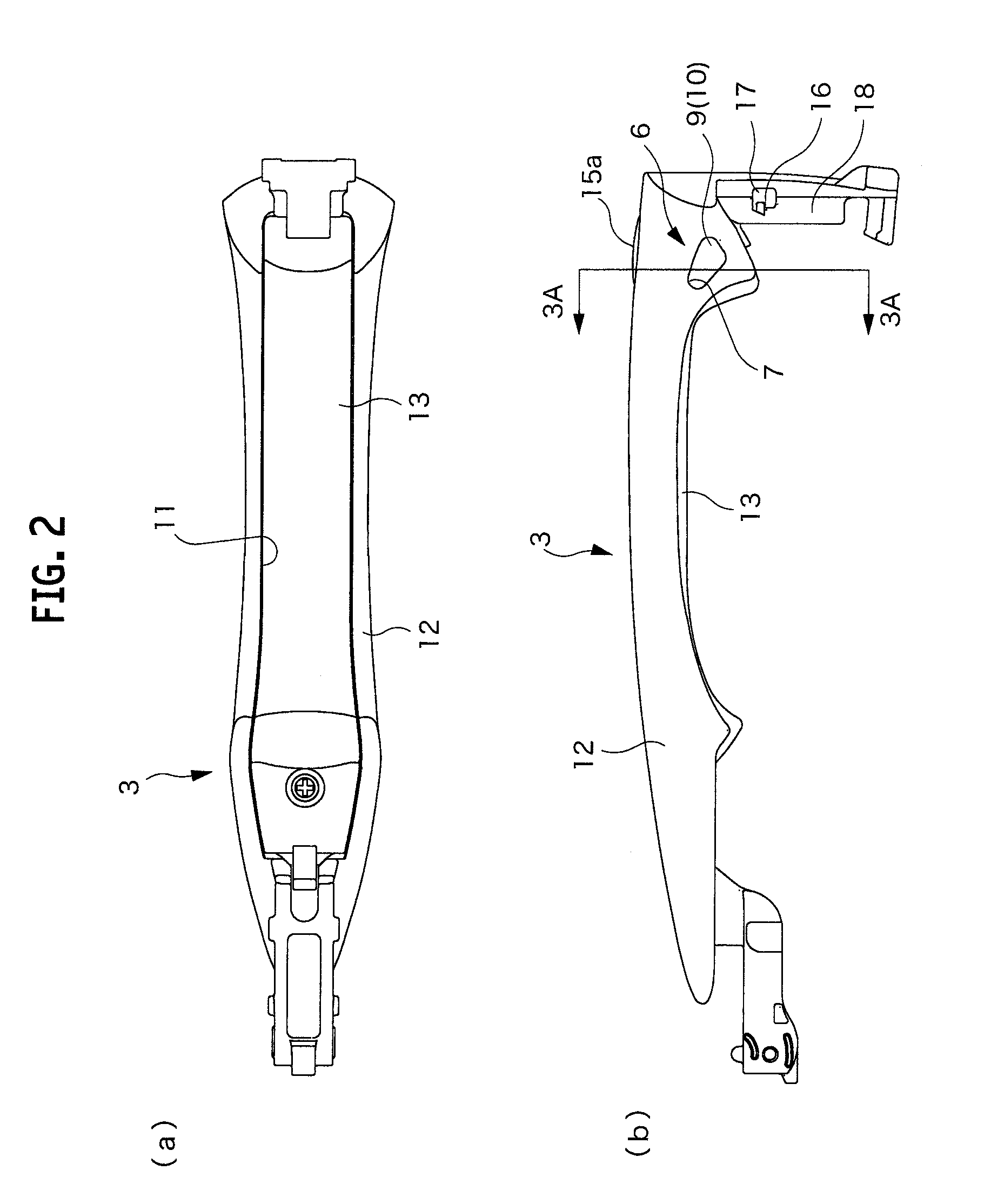
[0025]As shown in FIG. 1(a) to FIG. 6(c), a vehicle door handle apparatus includes: a handle base 2 secured to a vehicle door 1; and an operation handle 3 coupled to the handle base 2. In this embodiment, the operation handle 3 is formed as a so-called grip-type handle that allows one end to be coupled freely rotatably to the handle base, and is operated by gripping a grip portion 3a as a midpoint portion. The operation handle 3 is attached to the vehicle door 1 in a horizontal posture in which a left side in FIG. 1(a) is directed forward of a vehicle.

[0026]In the operation handle 3, an operation leg portion 18 is provided, which protrudes into an inside of the door 1 from an opposite end to a rotation end, and moves in a thickness direction following a rotation operation of the operation handle 3. Moreover, on the handle base 2, a lever 19 engaged with the operation leg portion 18 is axially supported about a rotation axis C19 so as to be freely rotatable. The lever is rotationally...


PUM


Abstract

A door handle apparatus includes: a handle base (2) secured to a vehicle door (1); an operation handle (3) freely rotatably coupled to the handle base (2); and a lighting device (6) including a light emitting element (5) that emits light by being fed with power through wire harnesses (4) inserted through an inside of the operation handle (3). An irradiation opening (7) is formed on a sidewall of the operation handle (3), which is opposite to the ground in a state where the operation handle (3) is attached onto the door (1). The lighting device (6) is formed in a lens portion (9) sealing the light emitting element (5) in cooperation with sealing resin (8), and is secured to the operation handle (3) by fitting, to the irradiation opening (7), a fitting protruding portion (10) having a shape coinciding with the irradiation opening (7).

Description

[0001]This is a National Phase Application filed under 35 U.S.C. §371 as a national stage of PCT / JP2010 / 055557, filed on Mar. 29, 2010, an application claiming the benefit under 35 U.S.C. §119 from Japanese Patent Application No. P2009-081583 filed on Mar. 30, 2009, the content of each of which is hereby incorporated by reference in its entirety.TECHNICAL FIELD[0002]The present invention relates to a vehicle door handle apparatus.BACKGROUND ART[0003]One described in Patent Document 1 is known as a door handle apparatus that performs foot lighting by fixing a lighting source (lighting device) to a door handle (operation handle) attached to a vehicle door.[0004]However, in the above-mentioned conventional example, since the operation handle is used while being exposed to the outside, there is a disadvantage that an occurrence of a short circuit and the like owing to entrance of rainwater, wash water and the like cannot be prevented if such a lighting device as an LED is only attached ...

Claims


Application Information

Patent Timeline
Patent Type & Authority Patents(United States)
IPC IPC(8): B60Q1/00B60J5/04E05B1/00E05B81/78E05B85/16
CPCB60Q1/2669E05B17/10E05B85/16Y10T16/458E05B81/76E05B79/02B60J5/04E05B1/00
Inventor TANAKA, TOMOYAIGETA, MAKOTO
Owner ALPHA
Learn More