Elastic shaft coupling with adaptive characteristics

a technology of elastic shaft and adaptive characteristics, applied in the direction of shafts, couplings, flexible shafts, etc., can solve the problems of reducing the service life affecting the operation range of the complete system, and the coupling stage still needs improvemen

Active Publication Date: 2013-08-27
CENTA ANTRIEBE KIRSCHEY GMBH
View PDF16 Cites 1 Cited by
  • Summary
  • Abstract
  • Description
  • Claims
  • Application Information

AI Technical Summary

Benefits of technology

[0036]FIG. 6 is a schematic view showing how a damping mass co...

Problems solved by technology

Two-stage couplings that take advantage of the effect of different characteristics of the coupling bodies for compensation of rotational vibrations perform their task substantially in a very reliable manner; however, they have the problem that here, on the one hand, the o...

Method used


Image

  • Elastic shaft coupling with adaptive characteristics
  • Elastic shaft coupling with adaptive characteristics
  • Elastic shaft coupling with adaptive characteristics

Examples


Embodiment Construction

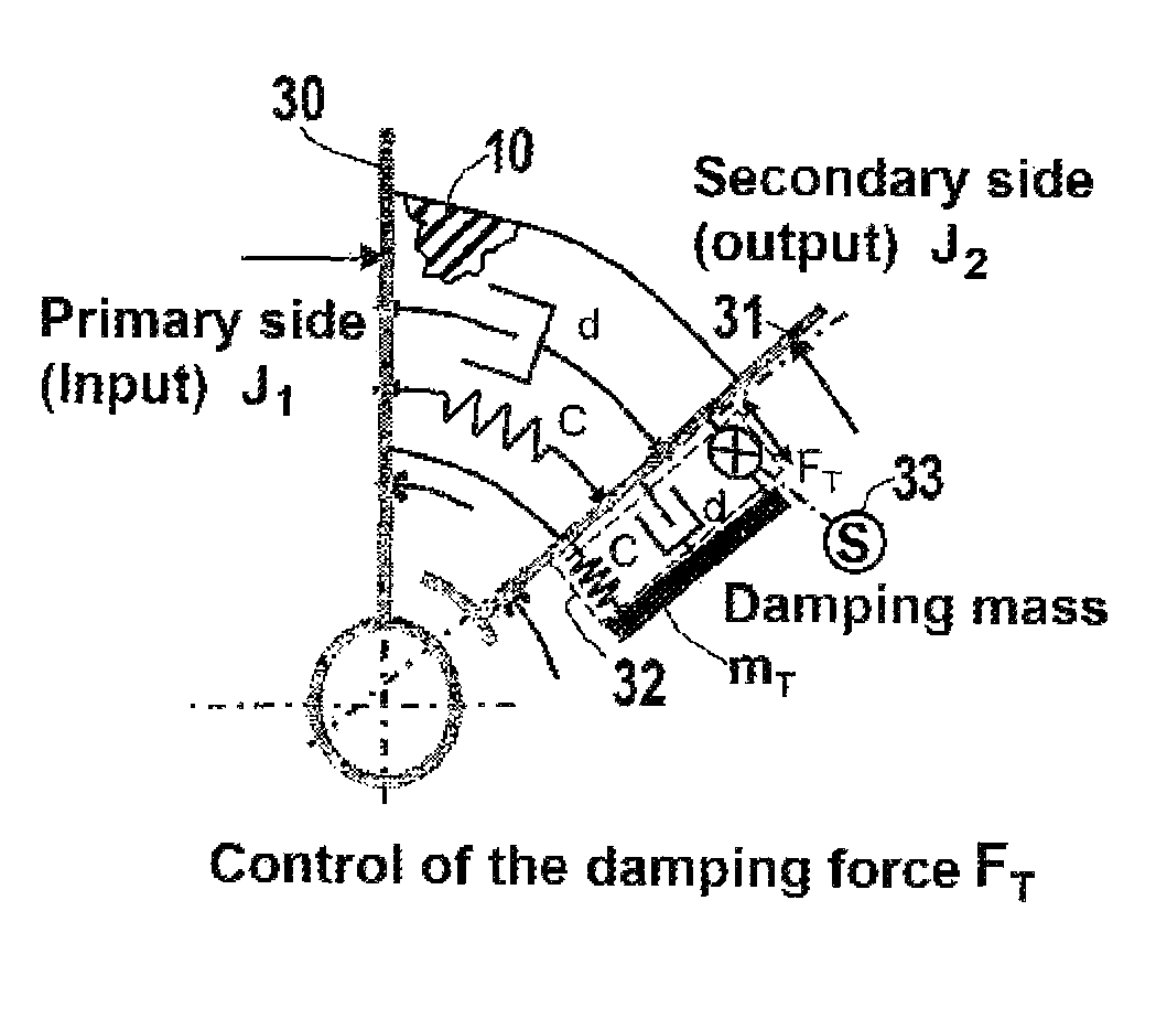
[0037]In the figures, a coupling body of an elastic shaft coupling is indicated at 10. It is connected between a drive-side connector 30 (see FIGS. 5 and 6) and an output-side connector indicated schematically at 31.

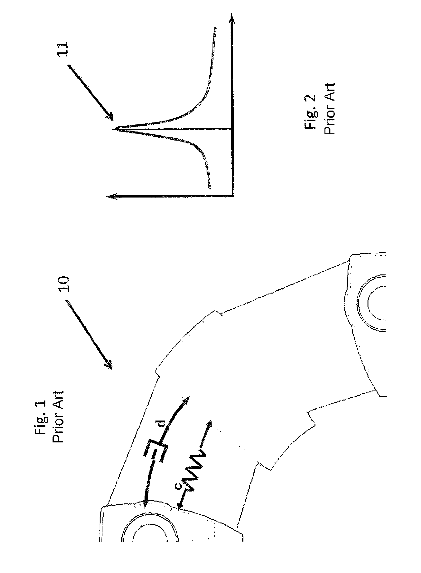
[0038]The coupling body 10 of the prior art shown in FIG. 1 consists of resilient material, preferably an elastomer (see FIG. 6). Depending on its composition, the elastomer has a constant elasticity c and a constant damping d.

[0039]The frequency diagram of FIG. 2 shows a possible torsional vibration curve of the coupling body in FIG. 1 plotted against frequency. The X-axis shows the frequency or speed and the Y-axis shows the amplification function, that is, in general, torque, force or distance. Peak vibration, which is to be avoided in a real system, is indicated at 11. Usually, a supercritical or subcritical position of the operating ranges is selected for this resonance peak. The frequency position for a coupling according to FIG. 1 is constant.

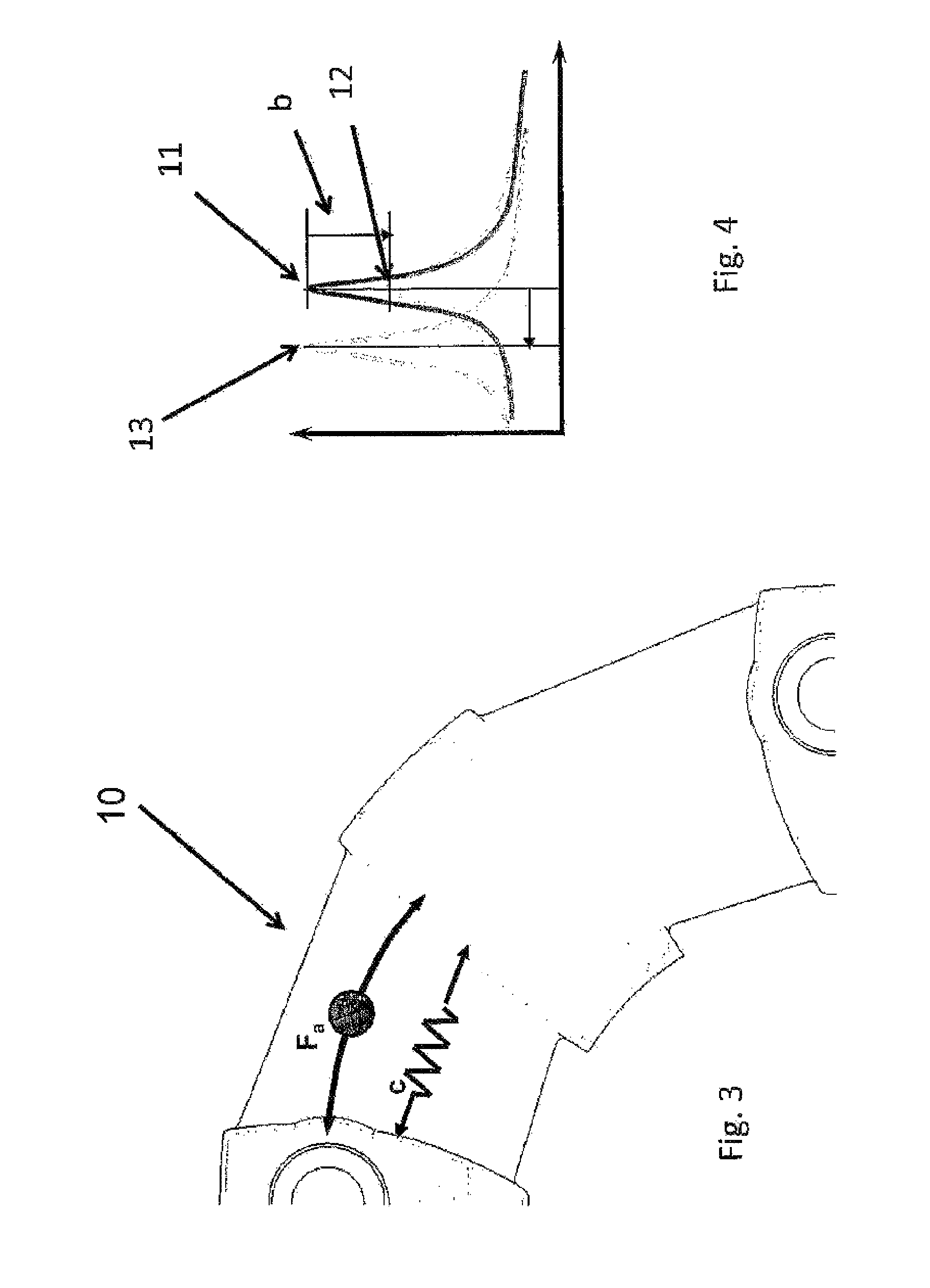
[0040]An actuator Fa ...


PUM


Abstract

An elastic shaft coupling has a resilient coupling body, a drive-side connector and an output-side connector connected to opposite sides of the coupling body, and an actively controllable damping mass. A connecting element connects the damping mass to the coupling body. Adjusting elements acting on the connecting element can influence how the shaft coupling compensates for torsional vibrations.

Description

CROSS REFERENCE TO RELATED APPLICATIONS[0001]This application is the US-national stage of PCT application PCT / DE2008 / 000963, filed 13 Jun. 2008, published 17 Dec. 2009 as WO2009 / 149676, and claiming the priority of PCT patent application PCT / DE2008 / 000963 itself filed 13 Jun. 2008.FIELD OF THE INVENTION[0002]The invention relates to an elastic shaft coupling with a resilient coupling body and a drive-side connector such as a mounting flange for securing the coupling to an engine flywheel and an output-side connector such as a mounting flange for securing the coupling to a shaft hub.BACKGROUND OF THE INVENTION[0003]Elastic shaft couplings of this type are known in numerous different embodiments with axial force flow or radial force flow, with one or more resilient coupling bodies that are connected in series or in parallel. Examples are the shaft couplings of DE 100 13 412 [U.S. Pat. No. 6,464,587] or DE 10 2005 055 605 [U.S. Pat. No. 7,497,782] that are published.[0004]Besides the c...

Claims


Application Information

Patent Timeline
IPC IPC(8): F16D27/00H02N2/00
CPCF16D3/72F16D3/64F16F15/124Y10T464/30
Inventor EXNER, JOCHEN
Owner CENTA ANTRIEBE KIRSCHEY GMBH
Why Eureka
Try Eureka