Transceiver

a technology of transceivers and receivers, applied in the field of transceivers, can solve the problems of shortening the transmittable range, and achieve the effects of reducing power consumption, preventing interference with other systems, and increasing transmission capacity

Active Publication Date: 2013-08-20
MAXELL HLDG LTD
View PDF16 Cites 7 Cited by
  • Summary
  • Abstract
  • Description
  • Claims
  • Application Information

AI Technical Summary

Benefits of technology

[0008]In contrast, in the 5 GHz band wireless communication, the electric wave in the 5 GHz band has a weaker tendency to go in straight lines than the electric wave in the millimeter wave band, the transmittable range is longer than in the millimeter wave band wireless communication and, so, the communication is performed more stably.
[0012]In view of the foregoing, it is an object of the present invention to provide a wireless transceiver capable of using multiple wireless methods at the same time for minimizing the above described problems involved in the millimeter wave band wireless communication and 5 GHz band wireless communication.
[0020]When the wireless communication is switched from the millimeter wave band wireless communication, whose communication status is degraded, to the 5 GHz band wireless communication, the present invention described above detects whether a channel shared in the 5 GHz band is usable, thus preventing interference with other systems.
[0021]In addition, in the 5 GHz band wireless communication where 20 MHz wide channels and 40 MHz wide channels are used, the present invention allows 40 MHz wide channels, which have a larger transmission capacity, to be used by priority.
[0022]In addition, when the wireless communication is switched to the 5 GHz band wireless communication, the present invention stops the millimeter wave band wireless communication to reduce power consumption.

Problems solved by technology

However, because the electric wave in the millimeter wave band has an extremely strong tendency to go in straight lines in the millimeter wave band wireless communication, the drawback is that the transmittable range becomes shorter; for example, the communication is blocked in a place where there is an obstacle object between the transmitting device and the receiving device.

Method used


Image

  • Transceiver
  • Transceiver
  • Transceiver

Examples


first embodiment

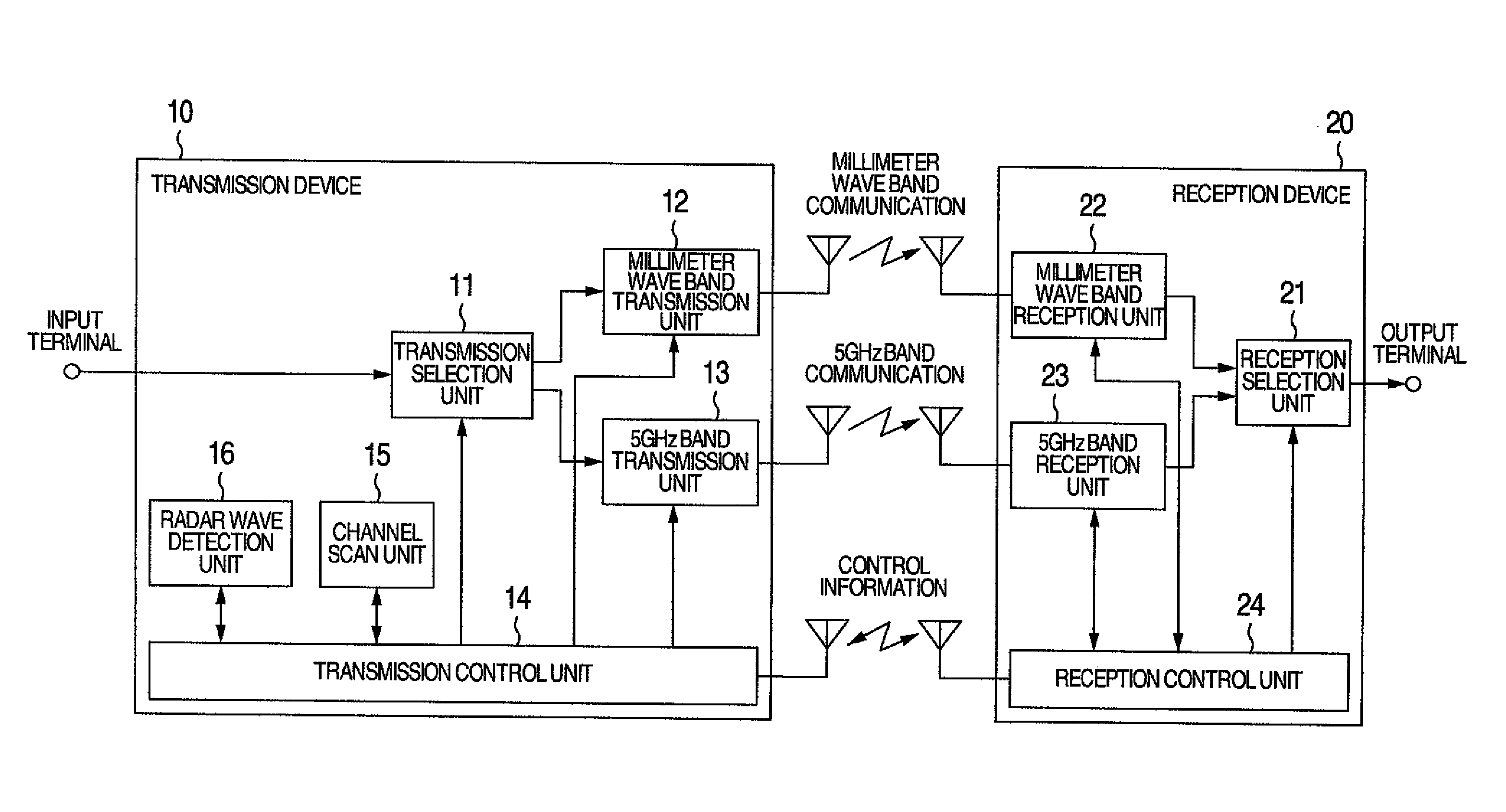
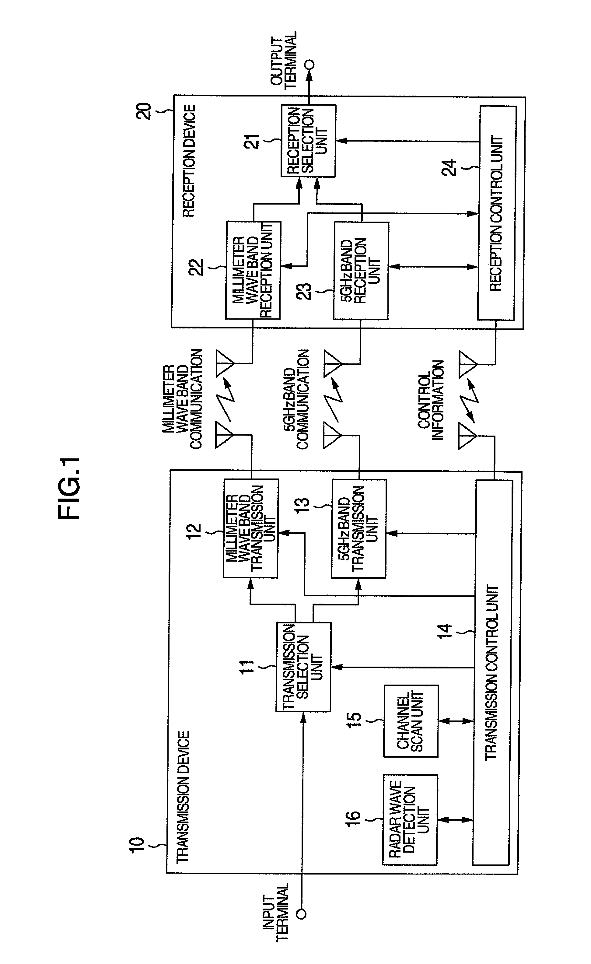
FIG. 1 is a block diagram showing the configuration of a wireless transceiver in the present invention.

[0037]Referring to FIG. 1, a transmission device 10 that functions as the HD stream signal transmitting side comprises a transmission selection unit 11, a millimeter wave band transmission unit 12, a 5 GHz band transmission unit 13, a transmission control unit 14, a channel scan unit 15, and a radar wave detection unit 16.

[0038]The transmission selection unit 11 receives, via the input terminal, an HD stream signal output from a broadcast reception device that receives a broadcast wave, a playback device such as a DVD (Digital Versatile Disk) or a BD (Blu-ray Disk), and a storage device such as an HDD (Hard Disk Drive). The transmission selection unit 11 supplies the received HD stream signal to either the millimeter wave band transmission unit 12 or the 5 GHz band transmission unit 13 or, in some cases, to both of them according to an instruction from the transmission control unit...

second embodiment

[0076]In the example of operation described in the second embodiment, the reception quality value of the millimeter wave band wireless communication is checked when the reception quality value of the 5 GHz band wireless communication is varied. The following describes another example of operation.

third embodiment

[0077]FIG. 6 is a block diagram showing the configuration of a wireless transceiver in the present invention. As shown in FIG. 6, the reception device 20 described above, a sensor sensing unit 31, and a display driving detection unit 32 are fixed internally or externally in a display 30 on which an HD stream signal, received by the reception device 20, is displayed. The sensor sensing unit 31, which includes a sensor capable of sensing the movement of an object such as a gravity sensor or an accelerometer, can detect that the display 30 is moved, for example, by human hands. The display driving detection unit 32 can detect that the direction of the display is changed, for example, by the remote control operation by the user if the display 30 has the function for allowing the user to mechanically change its direction.

[0078]FIG. 7 is a flowchart showing an example of the operation in the third embodiment of the present invention for switching the wireless communication from the 5 GHz ...


PUM


Abstract

The present invention provides a method for providing an optimal wireless communication method according to a change in a wireless communication environment. When the reception status is degraded while an HD stream signal, which uses a first wireless method, is transmitted and received, the method scans channels for which radar wave monitoring is not required and switches the transmission / reception to a second wireless method using free channel A. The method further scans channels for which radar wave monitoring is required and, if free channel B has a bandwidth wider than that of channel A is found, monitors channel B and if channel B is not used by a radar wave, switches the channel from channel A to channel B.

Description

INCORPORATION BY REFERENCE[0001]The present application claims priority from Japanese application JP2009-120470 filed on May 19, 2009, the content of which is hereby incorporated by reference into this application.BACKGROUND OF THE INVENTION[0002]The present invention relates to a transceiver capable of wireless transmission using multiple wireless methods.[0003]The speed of the wireless LAN (Local Area Network) method that is standardized as the IEEE802.11 standard has increased to the transmission speed of 100 Mbps or higher with the advent of IEEE802.11n. To increase the transmission speed, IEEE802.11n allows information to be transmitted in one of two frequency bands per channel: 20 MHz wide channel similar to that available in the existing standards IEEE802.11a / g and 40 MHz wide channel. In this wireless LAN method, two frequency bands, 2.4 GHz and 5 GHz, are available and, especially, many channels are available in the 5 GHz band without a wireless station license (in the desc...

Claims


Application Information

Patent Timeline
Patent Type & Authority Patents(United States)
IPC IPC(8): H04N5/38H04W4/00H04B17/00H04B1/00H04B1/74H04N7/173H04N21/426H04W84/10H04W88/06
CPCH04N5/38H04N21/43637H04N7/20
Inventor MURAKAMI, SHINICHIHODA, ISAOSHIROSUGI, TAKATOSHI
Owner MAXELL HLDG LTD
Why Eureka
Try Eureka