Ultrasonic receiving circuit

a technology of ultrasonic receiving circuit and occupancy sensor, which is applied in the direction of mechanical actuation of burglar alarms, using reradiation, instruments, etc., can solve the problems of limiting the ability to detect small-magnitude ultrasonic waves with a doppler shift, circuits are very sensitive to thresholds, and receive ultrasonic waves are difficult to distinguish from received ultrasonic waves

Active Publication Date: 2013-08-20
LUTRON TECH CO LLC
View PDF11 Cites 5 Cited by
  • Summary
  • Abstract
  • Description
  • Claims
  • Application Information

AI Technical Summary

Benefits of technology

[0014]An ultrasonic occupancy sensor for detecting presence or absence of an occupant in a space is also described herein. The occupancy sensor comprises an ultrasonic transmitting circuit having an ultrasonic transmitting element for transmitting ultrasonic waves, and an ultrasonic receiving circuit having an ultrasonic receiving element for generating an ultrasonic input signal. The ultrasonic receiving circuit further comprises an amplifier circuit for amplifying the input signal to generate an amplified signal, a synchronous rectifier for rectifying the amplified signal to generate a rectified signal, and a filter for filtering the rectified signal to generate a filtered signal. The synchronous rectifier may comprise a non-inverting amplifier and an inverting amplifier both receiving the amplified signal. The synchronous rectifier may further comprise a first analog switch coupled to an output of the non-inverting amplifier and a second analog switch coupled to an output of the inverting amplifier. The first and second analog switches may be electrically coupled together for forming the rectified signal. The occupancy sensor further comprises a controller operable to drive the ultrasonic transmitting circuit with a drive signal to control an ultrasonic transmission frequency of the transmitted ultrasonic waves. The controller may be operable to render the first and second analog switches conductive and non-conductive on a complementary basis, such the outputs of the analog switches may be mixed together to form the rectified signal. The controller receives the filtered signal and determines that the space is occupied if a magnitude of the filtered signal exceeds a threshold.
[0015]According to another embodiment of the present invention, the controller may drive the ultrasonic transmitting circuit with complementary drive signals to control an ultrasonic transmission frequency of the transmitted ultrasonic waves. The synchronous rectifier may also receive the drive signals from the controller, such that the filtered signal rises above the upper threshold or falls below the lower threshold when the frequency of the received ultrasonic waves is different than the frequency of the transmitted ultrasonic waves. The controller may be operable to determine that the space is occupied if the magnitude of the filtered signal rises above an upper threshold or falls below a lower threshold. In addition, the ultrasonic occupancy sensor may further comprise a low phase-noise oscillator circuit coupled to the controller for setting an internal operating frequency of the controller. The ultrasonic transmission frequency of the transmitted ultrasonic waves may be approximately equal to the internal operating frequency of the controller.

Problems solved by technology

One of the issues with detecting ultrasonic waves having a Doppler shift is that these received ultrasonic waves can be difficult to distinguish from the received ultrasonic waves that do not have a Doppler shift.
The drawback of this implementation is that the circuit is very sensitive to the thresholds of the comparators and only works on signals with an SIR greater than approximately −40 dB.
This implementation depends on the accuracy of the ADC of the microcontroller and is limited by numerical noise due to the ADC quantization and the numerical precision used to calculate the results, which thus limits the ability to detect small-magnitude ultrasonic waves that have a Doppler shift.
The limitation of this circuit is that the received ultrasonic signal must have a minimum amplitude to render the diode conductive, thus reducing the ability of the circuit to detect small-magnitude ultrasonic waves that have a Doppler shift.

Method used


Image

  • Ultrasonic receiving circuit
  • Ultrasonic receiving circuit
  • Ultrasonic receiving circuit

Examples


Embodiment Construction

[0026]The foregoing summary, as well as the following detailed description of the preferred embodiments, is better understood when read in conjunction with the appended drawings. For the purposes of illustrating the invention, there is shown in the drawings an embodiment that is presently preferred, in which like numerals represent similar parts throughout the several views of the drawings, it being understood, however, that the invention is not limited to the specific methods and instrumentalities disclosed.

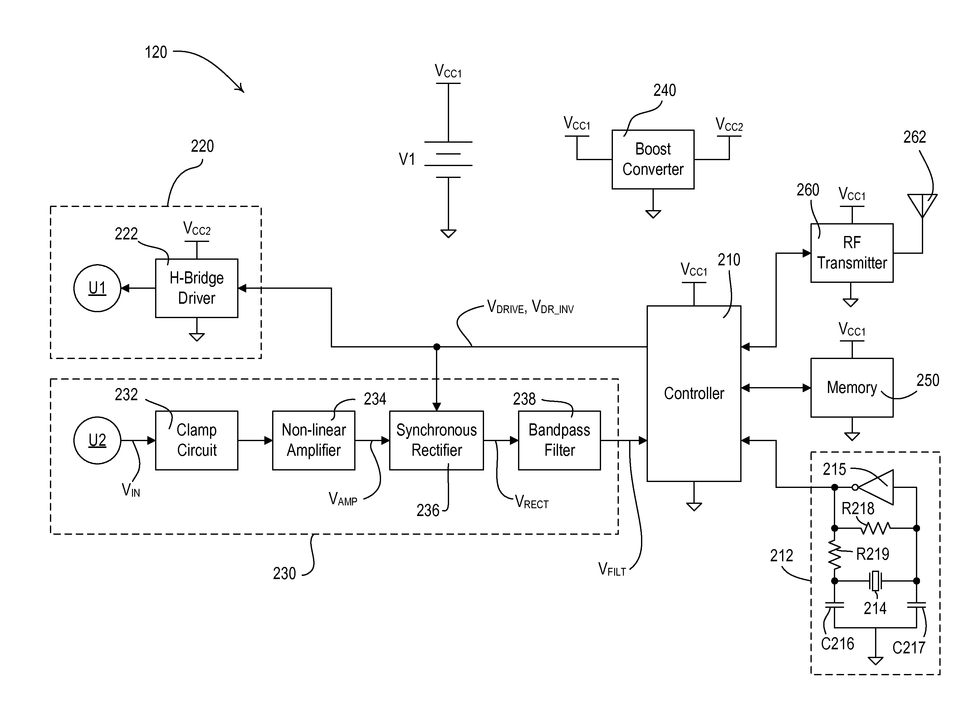
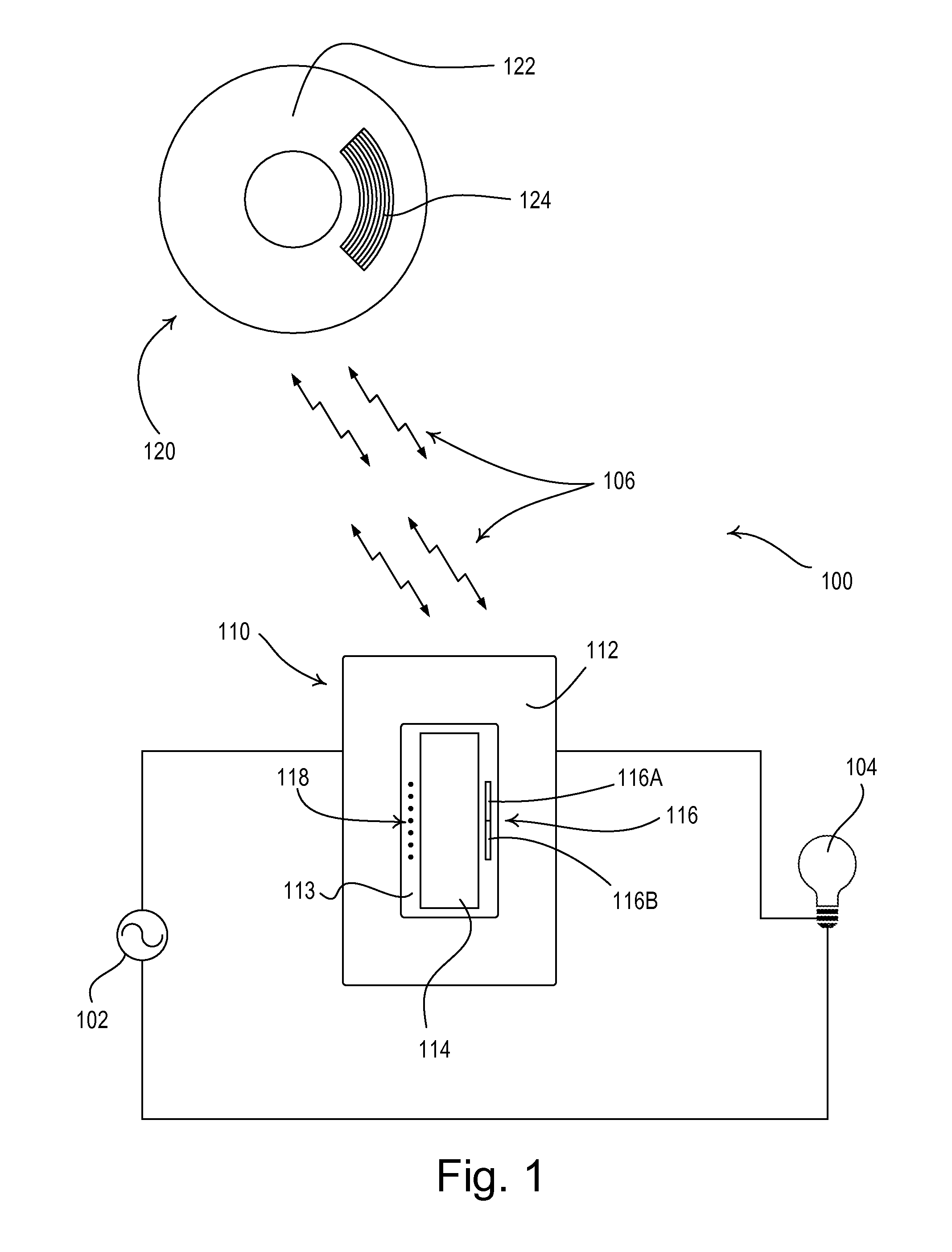
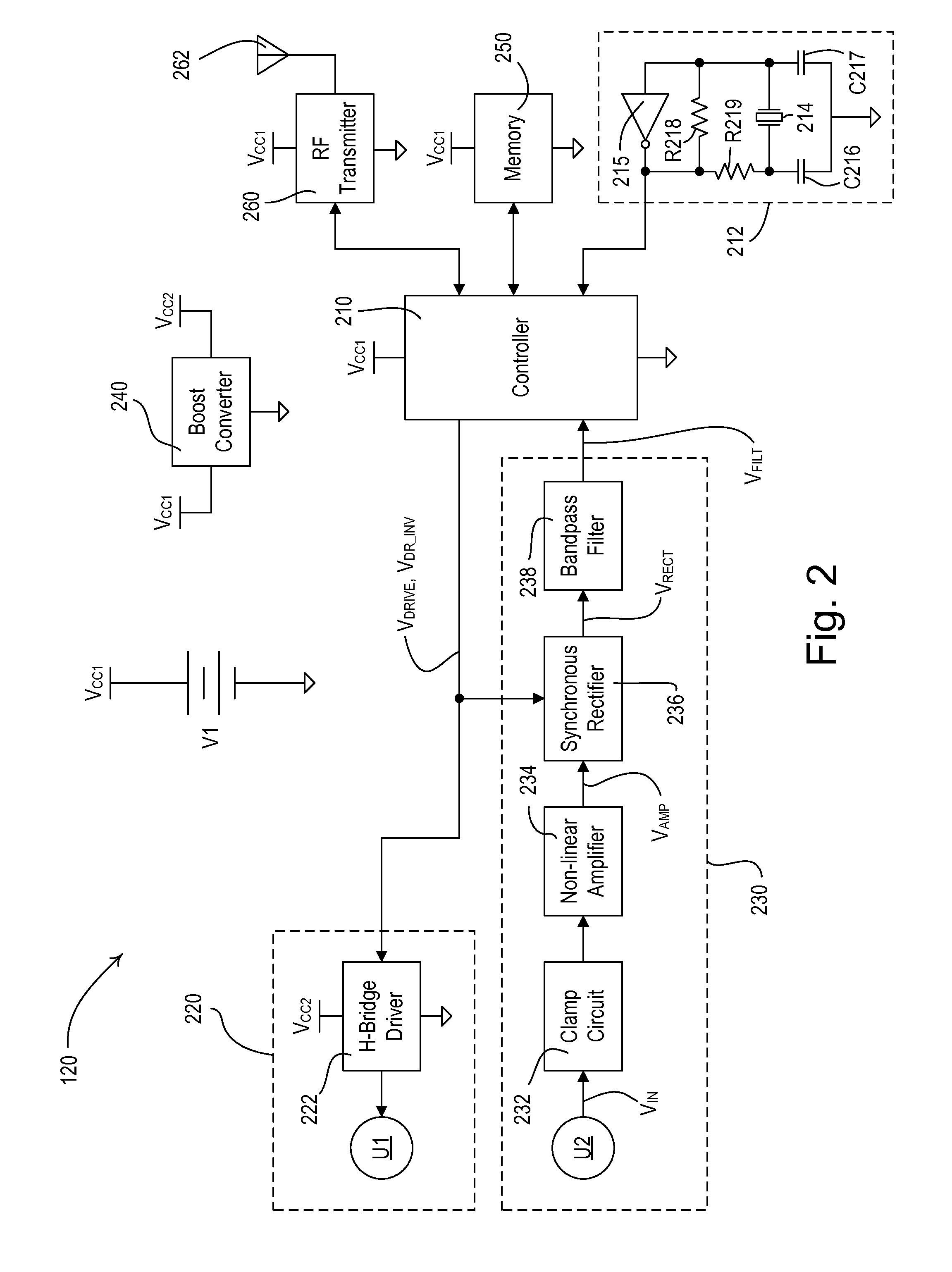
[0027]FIG. 1 is a simple diagram of a radio-frequency (RF) lighting control system 100 comprising a dimmer switch 110 and a remote ultrasonic occupancy sensor 120 according to an embodiment of the present invention. The dimmer switch 110 is adapted to be coupled in series electrical connection between an AC power source 102 and a lighting load 104 for controlling the amount of power delivered to the lighting load. The dimmer switch 110 may be adapted to be wall-mounted in a stan...


PUM


Abstract

An ultrasonic occupancy sensor for detecting presence or absence of an occupant in a space includes an ultrasonic receiving circuit having a synchronous rectifier that allows the circuit to detect small-magnitude ultrasonic waves having a Doppler shift. The sensor comprises an ultrasonic transmitter for transmitting ultrasonic waves at an ultrasonic operating frequency, and a controller that drives the transmitting circuit with complementary drive signals to control the ultrasonic operating frequency. The synchronous rectifier receives the drive signals from the controller and rectifies an amplified input signal to generate a rectified signal, which is filtered by a filter to generate a filtered signal. The controller receives the filtered signal and determines that the space is occupied if the magnitude of the filtered signal exceeds a threshold. The ultrasonic occupancy sensor may also include a low phase-noise oscillator circuit coupled to the controller for setting an internal operating frequency of the controller.

Description

CROSS-REFERENCE TO RELATED APPLICATIONS[0001]This application is a non-provisional application of commonly-assigned U.S. Provisional Application Ser. No. 61 / 316,011, filed Mar. 22, 2010, entitled ULTRASONIC RECEIVING CIRCUIT, the entire disclosure of which is hereby incorporated by reference.BACKGROUND OF THE INVENTION[0002]1. Field of the Invention[0003]The present invention relates to occupancy and vacancy sensors for detecting an occupancy or a vacancy in a space, and more particularly, to an ultrasonic receiving circuit for an occupancy or vacancy sensor.[0004]2. Description of the Related Art[0005]Occupancy and vacancy sensors are often used to detect occupancy and / or vacancy conditions in a space in order to control an electrical load, such as, for example, a lighting load. An occupancy sensor typically operates to turn on the lighting load when the occupancy sensor detects the presence of a user in the space (i.e., an occupancy event) and then to turn off the lighting load wh...

Claims


Application Information

Patent Timeline
Patent Type & Authority Patents(United States)
IPC IPC(8): G08B13/08
CPCG08B13/1627H05B37/0227Y02B20/44H05B47/115H05B47/13Y02B20/40G01S15/04
Inventor STEINER, JAMES P.
Owner LUTRON TECH CO LLC
Why Eureka
Try Eureka