
Coiled tubing unit

a technology of coiled tubing and coiled tubing, which is applied in the direction of drilling casings, drilling pipes, drilling rods, etc., can solve the problems of high requirements for well fields, large overall size of vehicles, and inability to be used in countries and regions, so as to reduce the total length and total weight, increase the winding capacity of coiled tubing, and ensure the effect of operating habits

Active Publication Date: 2019-06-25
JIANGHAN MASCH RES INST LTD CO OF CNPC +2
View PDF3 Cites 3 Cited by
  • Summary
  • Abstract
  • Description
  • Claims
  • Application Information

AI Technical Summary

Benefits of technology

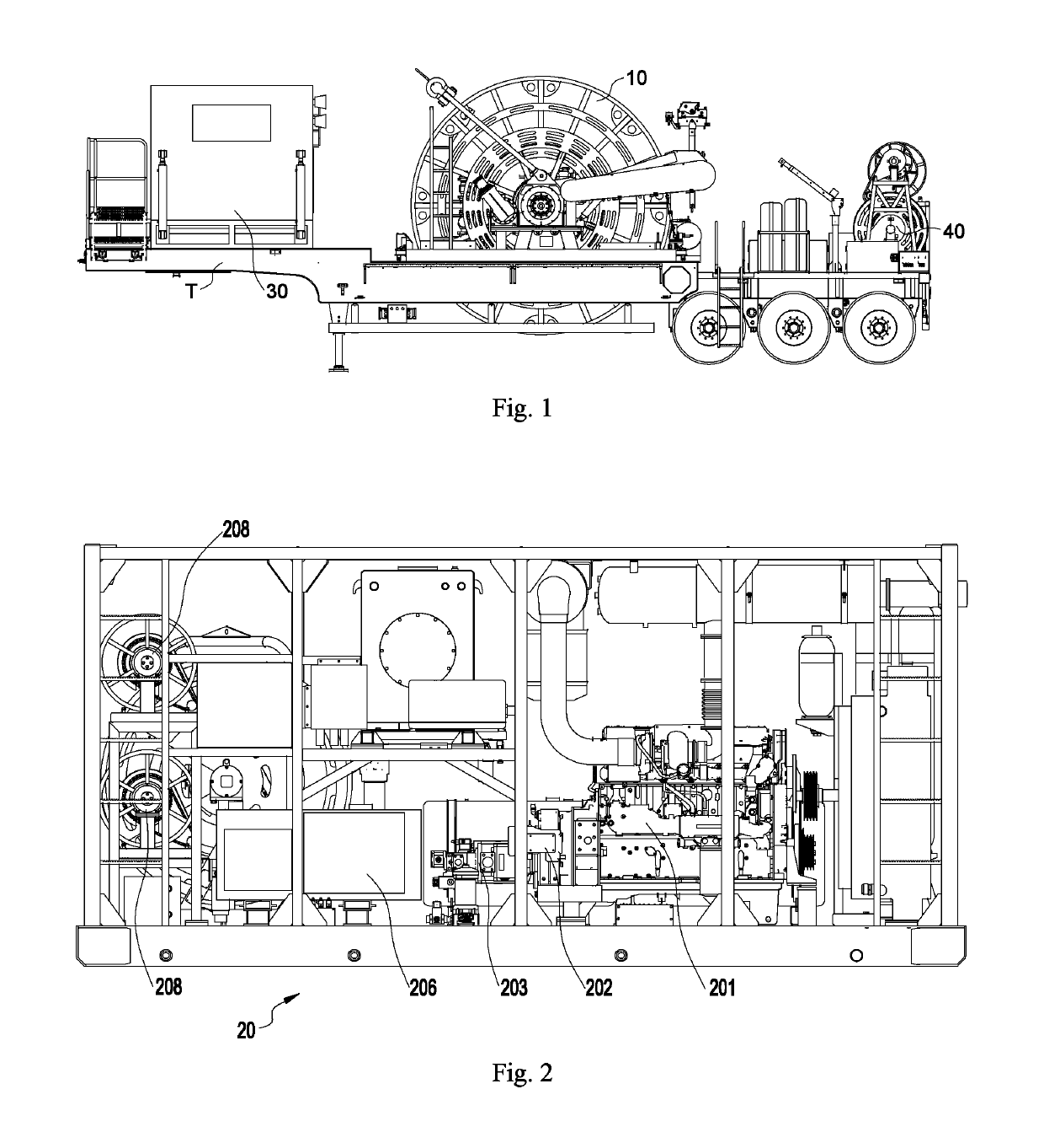
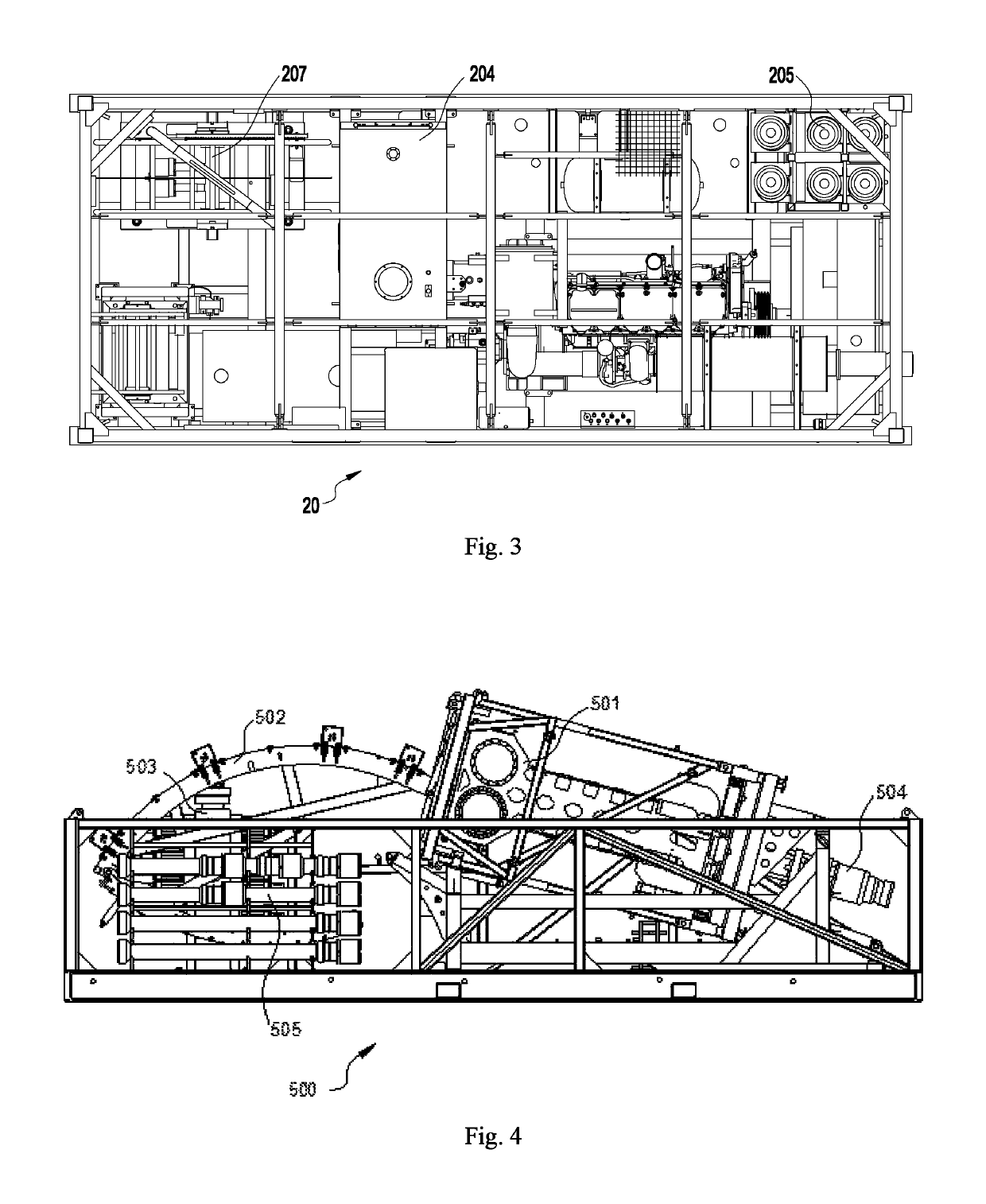
The present invention provides a coiled tubing unit that can be easily transported and deployed flexibly in well fields with limited space. The power system is arranged separately on a skid and transported separately, reducing the space and weight of the vehicle body and increasing the winding capacity of coiled tubing on the reel. The control cab and the coiled tubing reel are transported on one vehicle, allowing for convenient operation and observation. The power skid can be deployed conveniently and flexibly, allowing for the use of the coiled tubing unit in well fields with limited space. The invention also helps save costs and improve economic benefits.

Problems solved by technology

However, the coiled tubing unit which can hold coiled tubing above 2 in-6,000 m specification or 2 in-8,000 m specification are only available in a smaller number of countries such as USA and Canada, etc., but are not used in China and many other countries and regions yet.
Consequently, the vehicles are in a large overall size, extra high, extra wide, and extra heavy.
Such coiled tubing unit can be used in regions where the road conditions and transportation regulations permit, but can't be used in countries and regions where the road conditions are limited or the transportation regulations forbid.
Moreover, vehicles in extra-large dimensions have higher requirements for well fields, and can't be used in well fields where the space is limited.

Method used


Image

  • Coiled tubing unit
  • Coiled tubing unit
  • Coiled tubing unit

Examples


Embodiment Construction

[0025]Hereunder some embodiments of the present invention will be detailed with reference to the accompanying drawings. It should be understood that the embodiments described here are only provided to describe and explain the present invention, but shall not be deemed as constituting any limitation to the present invention.

[0026]In the present invention, unless otherwise specified, the terms that denote the orientations are used as follows, for example: “top”, “bottom”, “left” and “right” usually refer to “top”, “bottom”, “left” and “right” as shown in the accompanying drawings; “inside” and “outside” refer to inside and outside in relation to the profiles of the components.

[0027]The present invention provides a coiled tubing unit, which comprises a vehicle body T, a control cab 30, a coiled tubing reel 10 configured to wind coiled tubing, and a power skid 20 configured to supply power to the coiled tubing reel 10 and transported separately, wherein, the coiled tubing reel 10 and th...


PUM


Abstract

The present invention relates to the field of petroleum extraction equipment, and discloses a coiled tubing unit, which comprises a vehicle body (T), a control cab (30), a coiled tubing reel (10) configured to wind coiled tubing, and a power skid (20) configured to supply power to the coiled tubing reel (10) and transported separately, wherein, the coiled tubing reel (10) and the control cab (30) are mounted on the vehicle body (T). With the coiled tubing unit provided in the present invention, the total length and total weight of the vehicle body on which the coiled tubing reel is mounted are smaller and can meet the requirements for transportation in regions where smaller vehicle dimensions and weight are specified for transportation when coiled tubing in large diameter and / or great length is transported, and the coiled tubing unit is adaptive to the operating habits, and can be deployed flexibly so that it can be used in a well field where the space is limited.

Description

FIELD OF THE INVENTION[0001]The present invention relates to the field of petroleum extraction equipment, particularly to a coiled tubing unit.BACKGROUND OF THE INVENTION[0002]Presently, coiled tubing unit within 2 in-6,000 m specification are matured domestically and abroad, form a variety of structural types including vehicle-mounted structure, skid-mounted structure, and trailer-mounted structure, and can meet the requirements for use in different regions. However, the coiled tubing unit which can hold coiled tubing above 2 in-6,000 m specification or 2 in-8,000 m specification are only available in a smaller number of countries such as USA and Canada, etc., but are not used in China and many other countries and regions yet. Such coiled tubing unit usually use a semi-trailer-mounted structural type, and some of them use an all-in-one trailer-mounted structure (i.e., all devices are disposed on a semi-trailer) to reduce the number of vehicles required for transportation. Consequen...

Claims


Application Information

Patent Timeline
Patent Type & Authority Patents(United States)
IPC IPC(8): E21B19/22
CPCE21B19/22B65H2701/33
Inventor HE, HUIQUNYANG, GAOLIU, SHOUJUNLI, XUEHUIXIONG, GEZHANG, SHIBINHAO, JUNCAO, HEPINGDUAN, WENYIHU, ZHIQIANGYAN, JIAFUYANG, ZHIMINLIU, FEIZHOU, ZHONGCHENG
Owner JIANGHAN MASCH RES INST LTD CO OF CNPC
Learn More