Method and system for forming plug and play metal catalysts

a plug and play technology, which is applied in the field of method and system for forming plug and play metal catalysts, can solve the problems of affecting the effectiveness of the catalyst, reducing the surface area of the catalyst, and stopping the output of the catalys

Active Publication Date: 2013-08-13
UMICORE AG & CO KG +1
View PDF334 Cites 39 Cited by
  • Summary
  • Abstract
  • Description
  • Claims
  • Application Information

AI Technical Summary

Benefits of technology

The patent describes a method and system for making a metal catalyst. This involves using nanoparticles made of a catalyst material and a carrier. The nanoparticles are loaded into supports, which can have voids and pores, using a suspension. The supports can then be dried, exposed to heat and pressure, or a combination of both, to bond the nanoparticles onto the supports. This method allows for the efficient use of catalyst materials and carriers, resulting in a catalyst with improved activity and selectivity.

Problems solved by technology

As the particles coalesce into larger clumps, the particle sizes increase, the surface area of the catalyst decreases and the effectiveness of the catalyst is detrimentally affected.
During the transition period, output is stopped and overall throughput is adversely affected.
Also, platinum group metal catalysts are very expensive, and every addition of new supports comes at great cost.

Method used


Image

  • Method and system for forming plug and play metal catalysts
  • Method and system for forming plug and play metal catalysts
  • Method and system for forming plug and play metal catalysts

Examples


Embodiment Construction

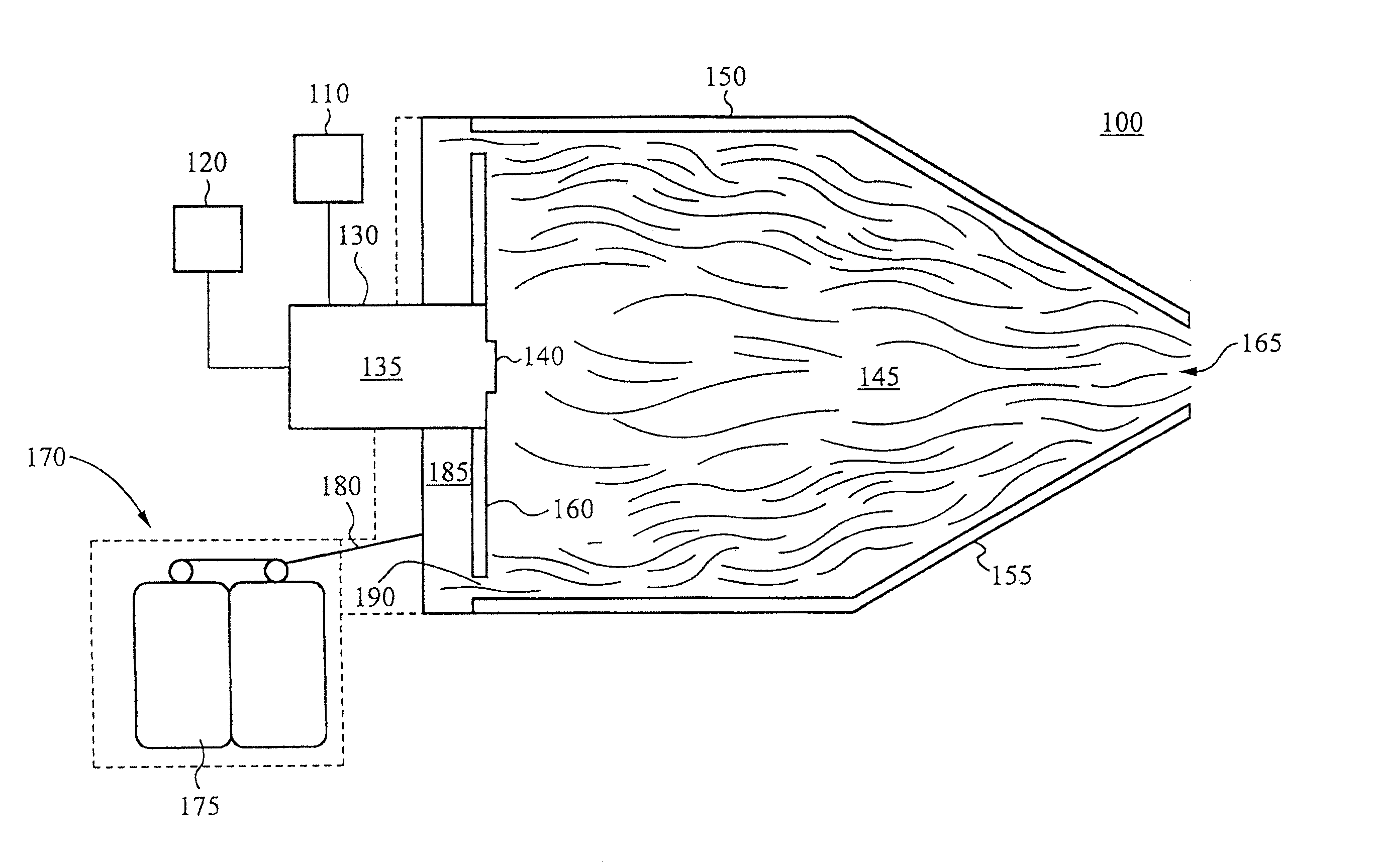
[0018]Reference will now be made in detail to implementations of the present invention as illustrated in the accompanying drawings. The drawings may not be to scale. The same reference indicators will be used throughout the drawings and the following detailed description to refer to identical or like elements. In the interest of clarity, not all of the routine features of the implementations described herein are shown and described. It will, of course, be appreciated that in the development of any such actual implementation, numerous implementation-specific decisions must be made in order to achieve the developer's specific goals, such as compliance with application, safety regulations and business related constraints, and that these specific goals will vary from one implementation to another and from one developer to another. Moreover, it will be appreciated that such a development effort will be a routine undertaking of engineering for those of ordinary skill in the art having the...


PUM

PropertyMeasurementUnit
Reynolds Numberaaaaaaaaaa
angleaaaaaaaaaa
oblique angleaaaaaaaaaa

Abstract

A metal catalyst is formed by vaporizing a quantity of metal and a quantity of carrier forming a vapor cloud. The vapor cloud is quenched forming precipitate nanoparticles comprising a portion of metal and a portion of carrier. The nanoparticles are impregnated onto supports. The supports are able to be used in existing heterogeneous catalysis systems. A system for forming metal catalysts comprises means for vaporizing a quantity of metals and a quantity of carrier, quenching the resulting vapor cloud and forming precipitate nanoparticles comprising a portion of metals and a portion of carrier. The system further comprises means for impregnating supports with the nanoparticles.

Description

RELATED APPLICATION(S)[0001]This Application is a divisional application claiming the benefit of priority from co-pending U.S. patent application Ser. No. 12 / 001,643, filed on Dec. 11, 2007, and entitled “METHOD AND SYSTEM FOR FORMING PLUG AND PLAY METAL CATALYSTS.” The co-pending U.S. patent application Ser. No. 12 / 001,643, filed on Dec. 11, 2007, and entitled “METHOD AND SYSTEM FOR FORMING PLUG AND PLAY METAL CATALYSTS” is hereby incorporated by reference.[0002]This patent Application claims priority under 35 U.S.C. §119(e) of the U.S. Provisional Patent Application Ser. No. 60 / 999,057, filed Oct. 15, 2007, and entitled “Nano Particle Catalysts” and which is hereby incorporated by reference in its entirety.BACKGROUND OF THE INVENTION[0003]In the oil refining and fine chemical industries, catalysts are required to transform one chemical or one material into another. For example, to make cyclohexane from benzene, benzene is passed through porous ceramic supports that have been impre...

Claims


Application Information

Patent Timeline
Patent Type & Authority Patents(United States)
IPC IPC(8): B01J21/00B32B15/02B05D1/36B05D3/02B05D3/00
CPCB01J37/0219B01J23/40B01J23/58B01J23/63B01J37/0203B01J37/0211B01J23/42C07C5/10C07C2521/04C07C2523/42C07C2601/14Y10S977/892B82Y40/00Y10T428/2982Y10T428/2991B01J37/349B01J35/394B01J35/393B01J35/23C07C13/18B01J37/08B01J37/04B01J21/08B01J21/04B01J23/10B01J21/063B01J23/02B01J31/02B01J8/00B01J35/19B01J35/40B01J23/83B01J21/066B01J27/02B01J27/14B01J27/20B01J27/24Y02P20/52B01J23/00B01J23/44B01J23/464B01J37/0215B01J37/0236
Inventor BIBERGER, MAXIMILIAN A.LEHMAN, JR., STEPHEN EDWARDKEVWITCH, ROBERT MATTHEWYIN, QINGHUAKINGSLEY, JESUDOS J.
Owner UMICORE AG & CO KG
Why Eureka
Try Eureka