Objecting positioning/fixing device
a positioning/fixing device and object technology, applied in the direction of positioning apparatus, metal-working machine components, manufacturing tools, etc., can solve the problems of deterioration of operability in fastening or releasing the clamp bolt, high manufacturing cost of the pallet positioning/fixing device, etc., and achieve the effect of increasing positioning precision
- Summary
- Abstract
- Description
- Claims
- Application Information
AI Technical Summary
Benefits of technology
Problems solved by technology
Method used
Image
Examples
embodiment 1
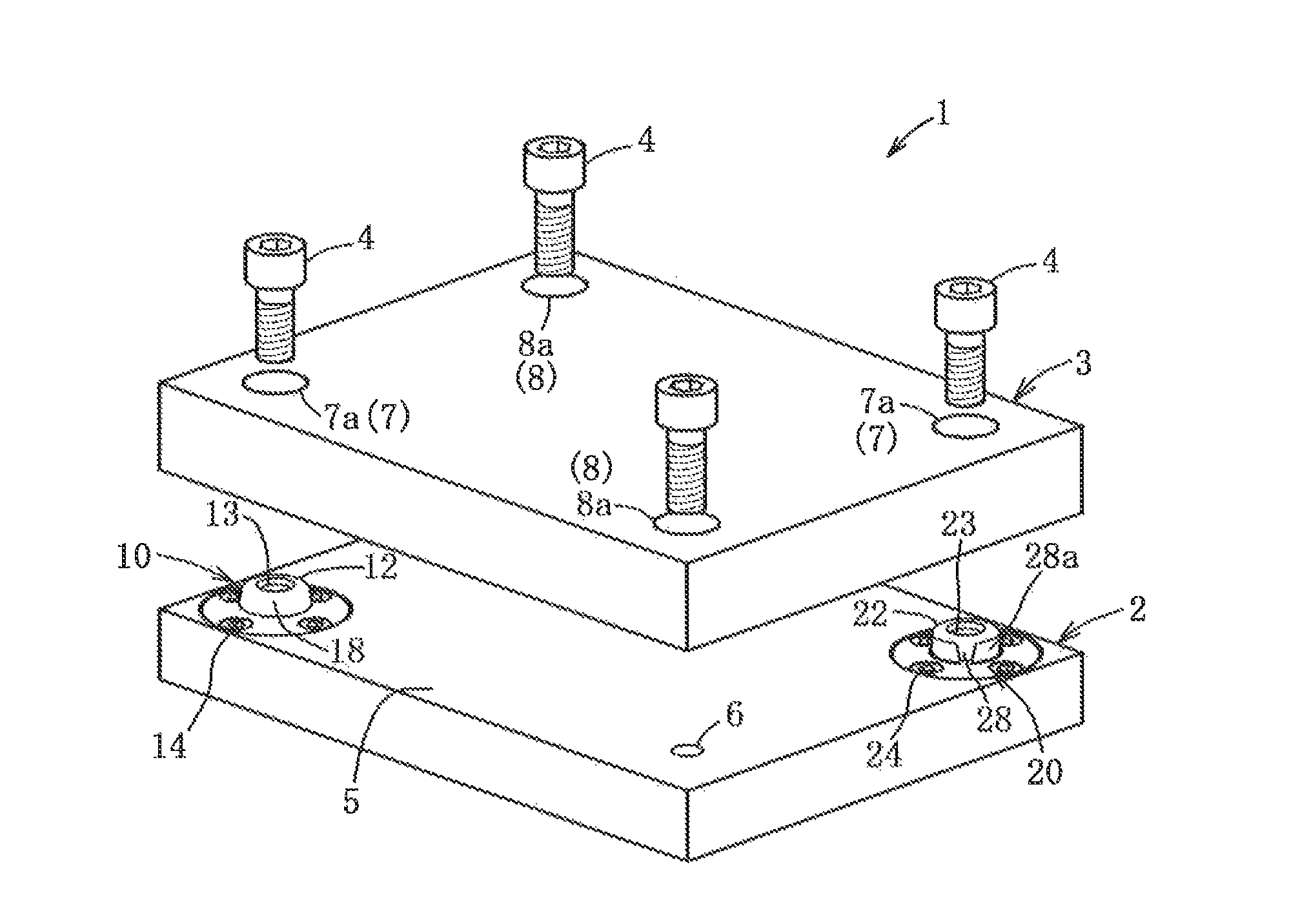
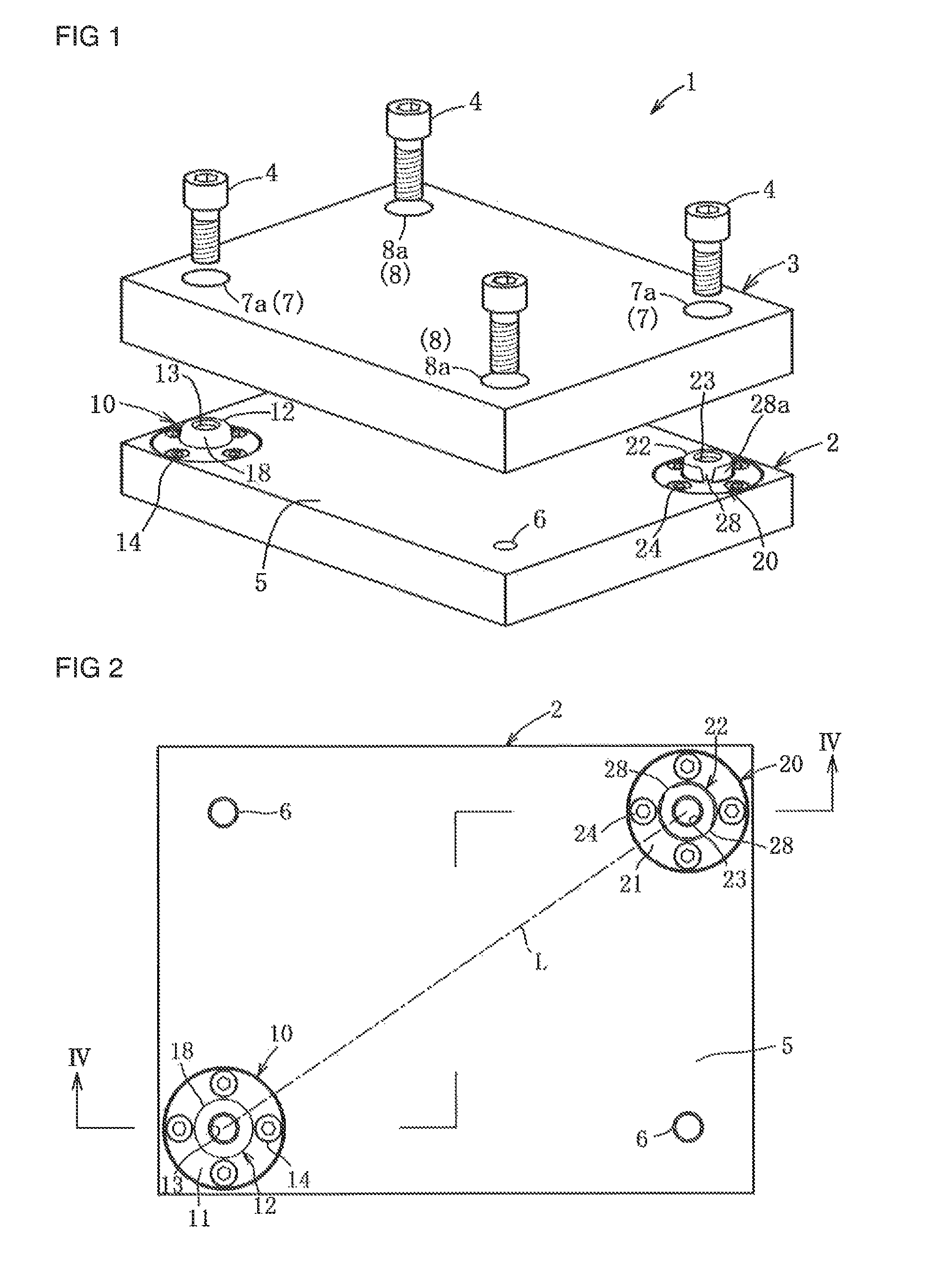
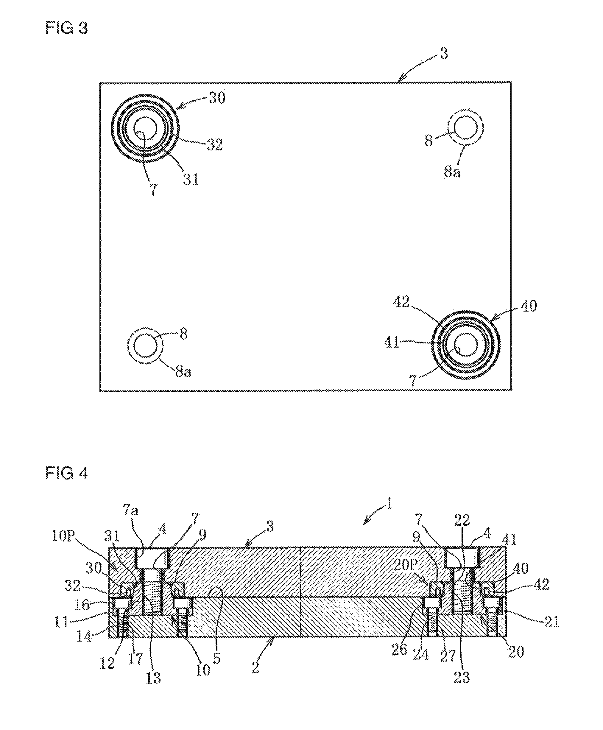
[0047]As shown in FIG. 1, the pallet positioning / fixing device 1 (corresponding to the “object positioning / fixing device”; hereafter referred to as the “positioning / fixing device”) of Embodiment 1 positions the pallet 3 (corresponding to the “target object”; hereafter referred to as the “work pallet”) for holding one or multiple works to be supplied for mechaning on the base member 2 in the horizontal and vertical direction, and fixes the work pallet by means of the clamp bolts.
[0048]Base member 2 is set in a fixed state on a machine tool table or the like. On the work pallet 3 fixed are one or multiple works (not shown) by means of the clamping device or multiple bolts (not shown), the work pallet 3 is transported onto the base member 2, and after being horizontally and vertically positioned and fixed, machining is executed to one or multiple works on the work pallet 3.
[0049]The positioning / fixing device 1 comprises; the base member 2, the work pallet 3, and four clamp bolts. The b...
embodiment 2
[0080]Next, an explanation will be made concerning the pallet positioning / fixing device 1A (corresponding to the “object positioning / fixing device”; hereafter referred to as the “positioning / fixing device”) of embodiment 2, based on FIG. 9-FIG. 11. However, the positioning / fixing device 1A, as same with the positioning / fixing device of embodiment 1, is a device which positions and fixes the work pallet (corresponding to the “target object”) for holding or attaching the work to be supplied firming by the machine tool. The same numerals are appended to the same elements as in embodiment 1, their explanation will he omitted, and an explanation will be made for only those elements having a different composition.
[0081]The positioning / fixing device 1A comprises; the base member 2A, the work pallet 3A, four clamp bolts 4, two bolt hole formation members 50 attached to the base member 2, and two seat forming members 30.
[0082]Base member 2A is provided with first and second reference members...
embodiment 3
[0089]Next, an explanation will be made concerning the pallet positioning / fixing device 1B of embodiment 3 (corresponding to the “object positioning / fixing device”; hereafter referred to as the “positioning / fixing device”) based on FIG. 12 and FIG. 13. The positioning / fixing device IB, is a device which positions and fixes the pallet 3B (corresponding to the “target object”) to the base member 2B as the cutting blade support pedestal for holding cutting tools in machine tools such as a lathe or the like, or other tools, products or work. Also, an explanation is omitted for such elements having numerals which are the same as for the same elements as in the first embodiment, and an explanation will be made only for different compositions.
[0090]The positioning / fixing device 1B comprises; the base member 2B, the pallet 3B, and two clamp bolts 4B. The base member 2B and the pallet 3B are respectively composed with the thick steel plate member having a elongated rectangular shape. The ent...
PUM
 Abstract
Description
Claims
Application Information
 - R&D
- Intellectual Property
- Life Sciences
- Materials
- Tech Scout
- Unparalleled Data Quality
- Higher Quality Content
- 60% Fewer Hallucinations
Browse by: Latest US Patents, China's latest patents, Technical Efficacy Thesaurus, Application Domain, Technology Topic, Popular Technical Reports.
© 2025 PatSnap. All rights reserved.Legal|Privacy policy|Modern Slavery Act Transparency Statement|Sitemap|About US| Contact US: help@patsnap.com


