
Method for using a multi-tune transceiver

a multi-tune transceiver and multi-tune technology, applied in the direction of pulse technique, amplitude demodulation, line-faulst/interference reduction, etc., can solve the problems of additional coexistence drawbacks, crystal reference and power management remain relatively limited, and cost savings beyond. , to achieve the effect of reducing size and power consumption, reducing cost and footprint, and increasing integration level

Active Publication Date: 2013-08-06
NXP BV
View PDF5 Cites 8 Cited by
  • Summary
  • Abstract
  • Description
  • Claims
  • Application Information

AI Technical Summary

Benefits of technology

The present invention provides a solution to the issue of coexistence between different tuners in wireless consumer products such as mobile phones and car radios. The invention uses a multi-tuner transceiver that reduces interference and distortion between tuners while also reducing power consumption and cost. The invention uses a single oscillator and a divider to create overlapping sub-bands that cover the entire reception band. This results in efficient use of frequency spectrum and reduced power dissipation. The technical effects of this invention include improved performance, reliability, and reduced costs of wireless products with multiple tuners.

Problems solved by technology

Unfortunately, despite the advantages of concurrent operation of features the potential cost savings beyond IC package, crystal reference and power management remain relatively limited.
Moreover, concurrent operation of transceivers in close proximity, or on the same IC, brings additional coexistence drawbacks.
The most severe coexistence problem is crosstalk between tuner sections.
For example, mutual coupling between two oscillators in two separate tuners can cause interference and distortion in both receivers.
Moreover, despite the availability of power from car batteries, excessive power dissipation in one IC is still not acceptable.
Additionally a large chip area of the combined functions leads to a lower yield and therefore higher costs.
The combination of large chip area and power dissipation makes the IC packages expensive.

Method used


Image

  • Method for using a multi-tune transceiver
  • Method for using a multi-tune transceiver
  • Method for using a multi-tune transceiver

Examples


Embodiment Construction

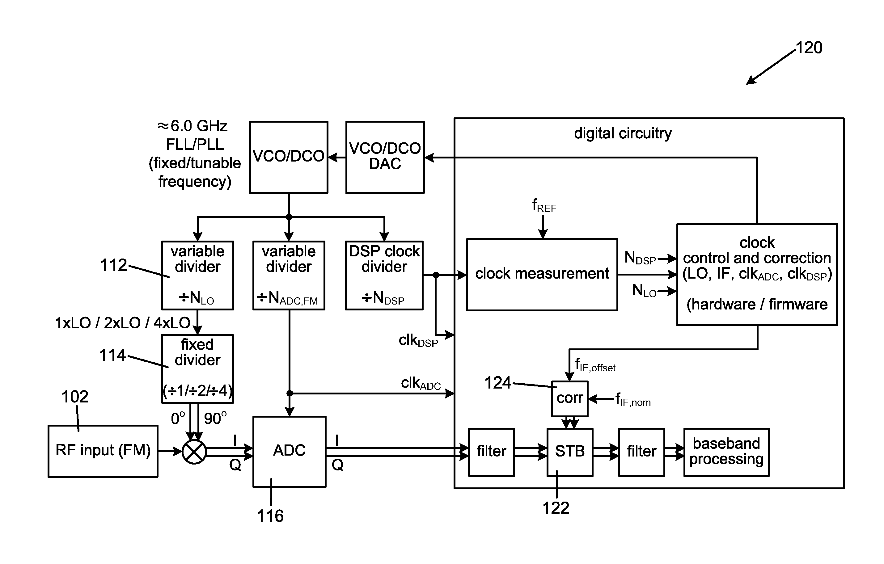
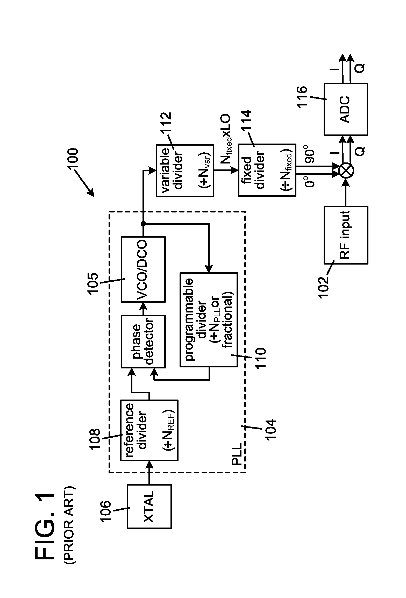
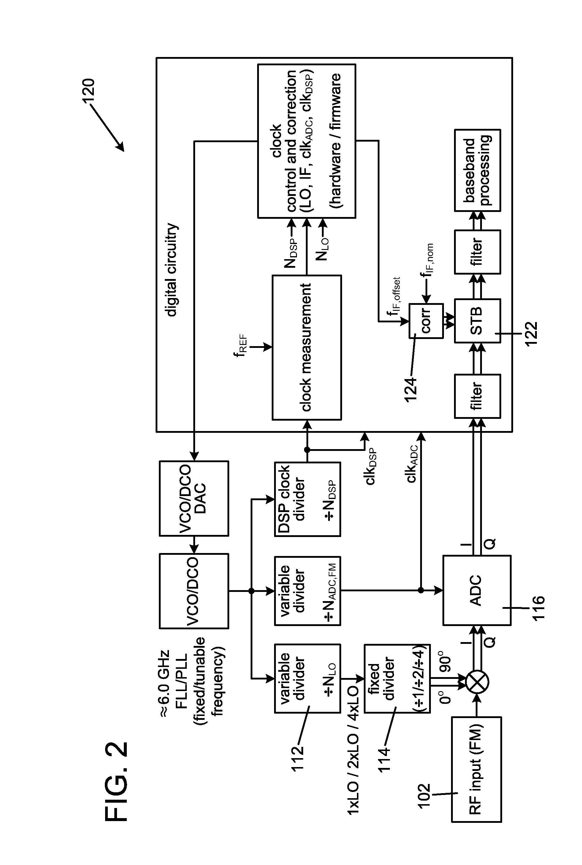
[0019]In general, LO (local oscillator) generation and ADC (analog-to-digital converter) functions play an important role in the method of the present invention to multi-tuner receiver implementation. ADCs normally have a bandwidth that is only wide enough to be able to handle one channel. FIG. 1 shows a simplified low-IF (intermediate frequency) receiver block diagram 100 that describes a LO generation scheme in more detail. In general, the low IF is the difference between the LO frequency and the RF input 102 which means for FM applications the LO frequency should be close to the frequency of the FM band. For FM broadcast reception, the system parameters include the integrated PLL 104, shown inside the dotted box that has an integrated VCO / DCO 105 in the 2-7 GHz range. Frequency steps are often determined by the crystal reference (XTAL) frequency 106, the reference divider 108 and the programmable divider settings 110 that chooses the VCO frequency. Because the oscillator runs at ...


PUM


Abstract

The method is for using a multi-tune transceiver. A single oscillator (VCO / DCO) is provided that is electronically connected to a divider. An input channel is provided that is in communication with the divider and an analog-to-digital converter. The input channel has a first bandwidth and the converter has a second bandwidth that is broader than the first bandwidth. The single oscillator (VCO / DCO) operates at a frequency higher than frequencies inside the reception band such as the FM band. The divider divides the frequency of the single oscillator that is used as input when producing overlapping sub-bands that cover the entire reception band.

Description

PRIOR APPLICATION[0001]This application is a U.S. national phase application based on International Application No. PCT / US10 / 060946, filed 17 Dec. 2010.TECHNICAL FIELD[0002]The invention relates to a method for using a multi-tune transceiver.BACKGROUND AND SUMMARY OF THE INVENTION[0003]Many wireless consumer products provide an increasing number of features and functions while the size and power consumption is decreased. This development has been primarily due to a higher integration level enabled by advances in sub-micron technology. For example, today's mobile telephones have more features such as FM radio TRX, Bluetooth and GPS as standard features. This was not the case a couple of years ago. This trend of adding new features to the mobile telephones is likely going to continue such as by adding features related to WiFi, DVB-H and NFC (Near Field Communication). At a low attachment rate, these wireless features are often implemented as separate integrated circuits (ICs). However...

Claims


Application Information

Patent Timeline
Patent Type & Authority Patents(United States)
IPC IPC(8): H04B1/00
CPCH03L7/099H03L7/104H04B1/0082H04B1/403H04B1/30
Inventor KIANUSH, KAVEGIERENZ, VOLKERVAN DER PLOEG, HENDRIK
Owner NXP BV
Learn More