Electrical load driving apparatus
a technology of electric load and driving apparatus, which is applied in the direction of logic circuit coupling/interface arrangement, pulse technique, instruments, etc., can solve the problems of over conventional electrical load driving apparatus, short circuit, and short circuit of current supply to electrical load, so as to achieve a large current burden
- Summary
- Abstract
- Description
- Claims
- Application Information
AI Technical Summary
Benefits of technology
Problems solved by technology
Method used
Image
Examples
first embodiment
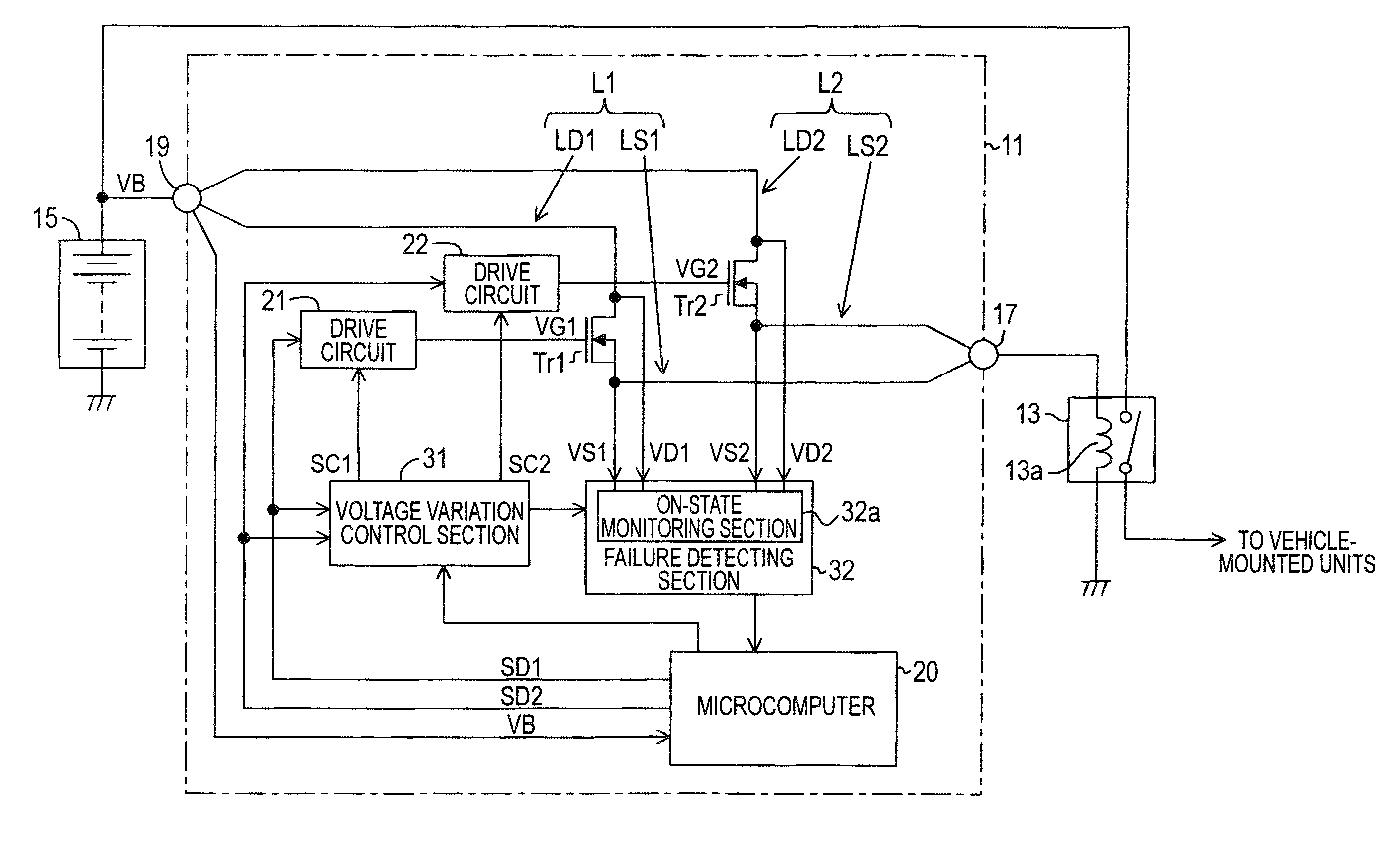
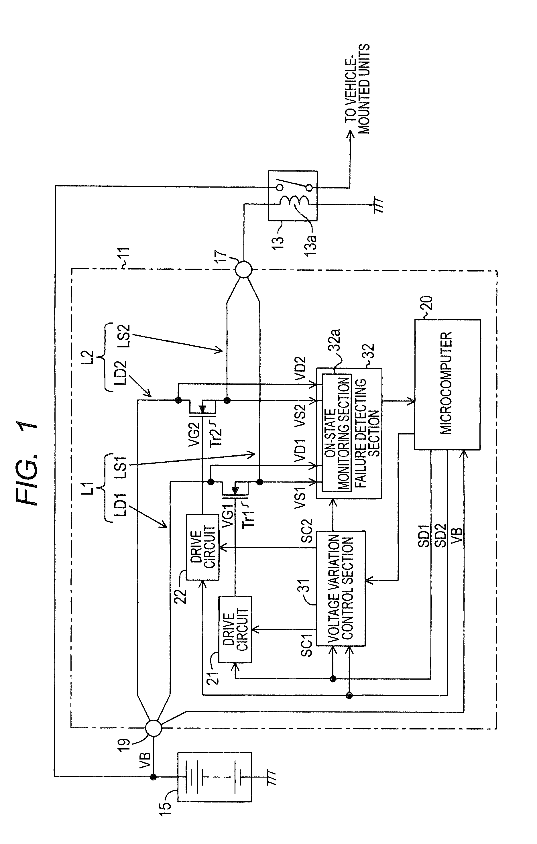
[0029]FIG. 1 is a diagram showing the structure of an ECU 11 as an electrical load driving apparatus according to a first embodiment of the invention.
[0030]The ECU 11 is mounted on a vehicle to turn on and off a relay 13 mounted on the vehicle by passing a current to a coil 13a of the relay 13. When the relay 13 is turned on, a battery voltage VB of a battery 15 is supplied to various vehicle-mounted units and devices related to the ignition system of the vehicle as a power supply voltage. More specifically, the ECU 11 turns on the relay 13 when a vehicle driver operates the ignition switch of the vehicle to supply the battery voltage VB to the various vehicle-mounted units and devices, and turns off the relay 13 when the vehicle driver turns off the ignition switch on condition that a predetermined power supply stop condition is satisfied.
[0031]In this embodiment, the relay coil 13a of the relay 13 is high side driven by the ECU 11. Accordingly, one end of the relay coil 13a is con...
second embodiment
[0093]Next, a second embodiment of the invention is described.
[0094]The ECU 11 of the second embodiment is different from that of the first embodiment in the following points (1) and (2).
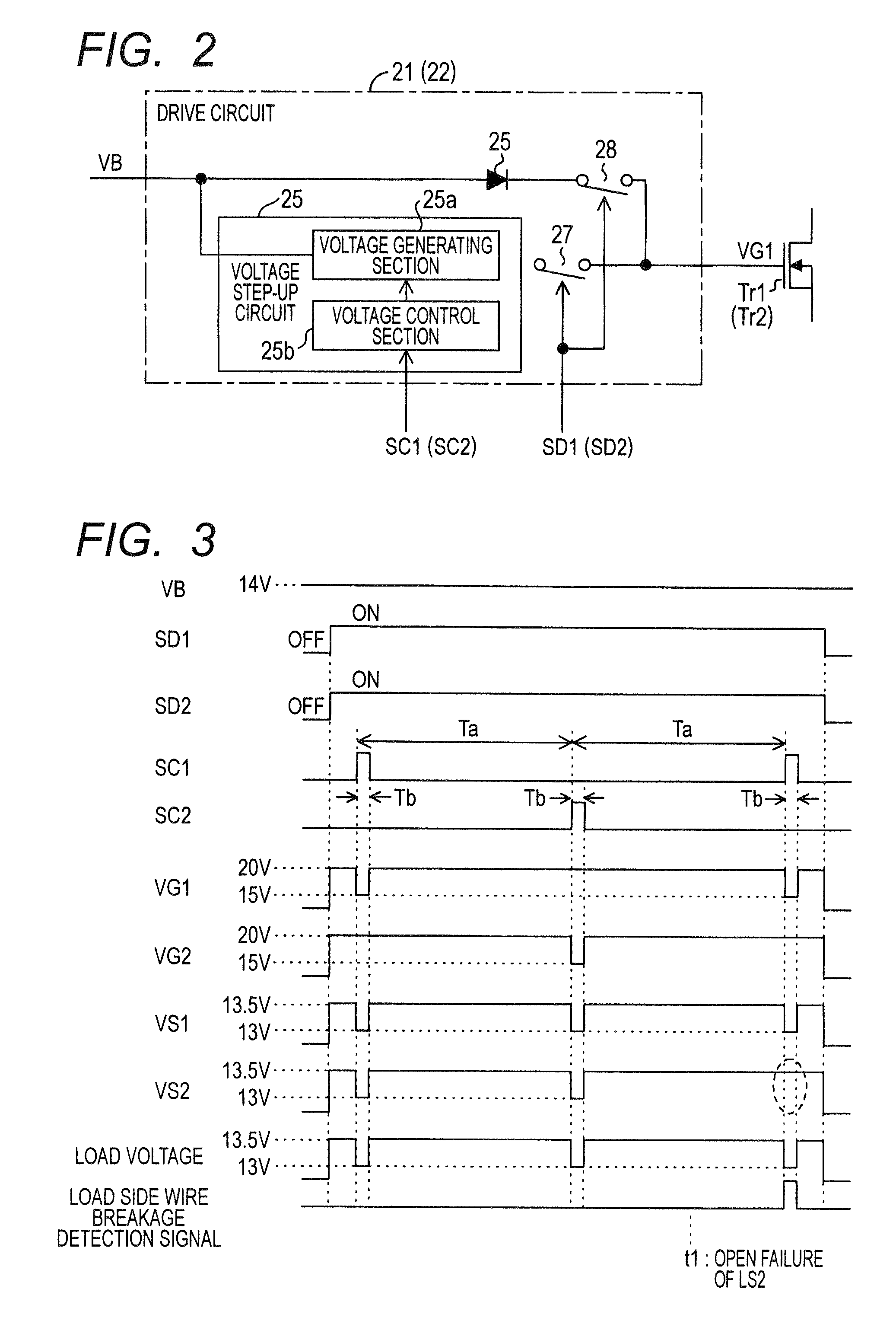
[0095](1) The voltage variation control section 31 sets the voltage variation command signals SC1 and SC2 to the high or low level not only in the pattern shown in FIG. 3, but also in the pattern shown in FIG. 6.
[0096]In the second embodiment, after a first check period in which the voltage variation command signals SC1 and SC2 are set to the high level alternately during the predetermined time Tb at the time intervals of the time Ta as shown in FIG. 3 is generated 2N times (N being an integer larger than or equal to 1), that is after each of the voltage variation command signals SC1 and SC2 is changed to the high level N times, a second check period in which both the voltage variation command signals SC1 and SC2 are set to the high level at the same time during the predetermined time Tb at regular ...
PUM
 Abstract
Description
Claims
Application Information
 - R&D
- Intellectual Property
- Life Sciences
- Materials
- Tech Scout
- Unparalleled Data Quality
- Higher Quality Content
- 60% Fewer Hallucinations
Browse by: Latest US Patents, China's latest patents, Technical Efficacy Thesaurus, Application Domain, Technology Topic, Popular Technical Reports.
© 2025 PatSnap. All rights reserved.Legal|Privacy policy|Modern Slavery Act Transparency Statement|Sitemap|About US| Contact US: help@patsnap.com


