
Connecting arrangement and connecting method, in particular by way of non-positive connection on all sides

Active Publication Date: 2013-07-30
NORD LOCK AG
View PDF17 Cites 30 Cited by
  • Summary
  • Abstract
  • Description
  • Claims
  • Application Information

AI Technical Summary

Benefits of technology

This patent is for a new and improved way to connect components together using expansion bolts. These bolts have a conical clamping element that can be expanded to create a strong and rigid connection. This design can handle larger manufacturing tolerances and reduces manufacturing costs. Additionally, a washer can be used to prevent damage to sensitive surfaces. The new design allows for real radial pre-clamping and avoids plastic deformations, making it easier to disassemble and reuse the components for maintenance. Overall, this invention offers a more efficient and reliable method for connecting components.

Problems solved by technology

These connecting elements can only be clamped and released with difficulty, however, due to their size.
Considerable manufacturing effort must be encountered with positively connecting connecting elements, which clamp two components to be connected.
Moreover, unwieldy and expensive tools are necessary for tightening and releasing screws and nuts of large connecting elements.
The use of a slugging wrench is carried out without control and is very accident-prone.
The use of a torque converter results in very high friction and is imprecise.
The use of hydraulic tools requires a lot of space and results in only little usage of the materials.
A further drawback with positively connecting connecting elements is that they are problematic to service and maintain, because specialized tools and methods are required to release them again.
Often, the connecting elements must even be destroyed, for example cut off, to remove them, which is often only possible with expensive and time-consuming improvisation.
Axial pre-clamping forces are however not possible.
However, a travel distance / stroke is neither adjustable nor limited.

Method used


Image

  • Connecting arrangement and connecting method, in particular by way of non-positive connection on all sides
  • Connecting arrangement and connecting method, in particular by way of non-positive connection on all sides
  • Connecting arrangement and connecting method, in particular by way of non-positive connection on all sides

Examples


second embodiment

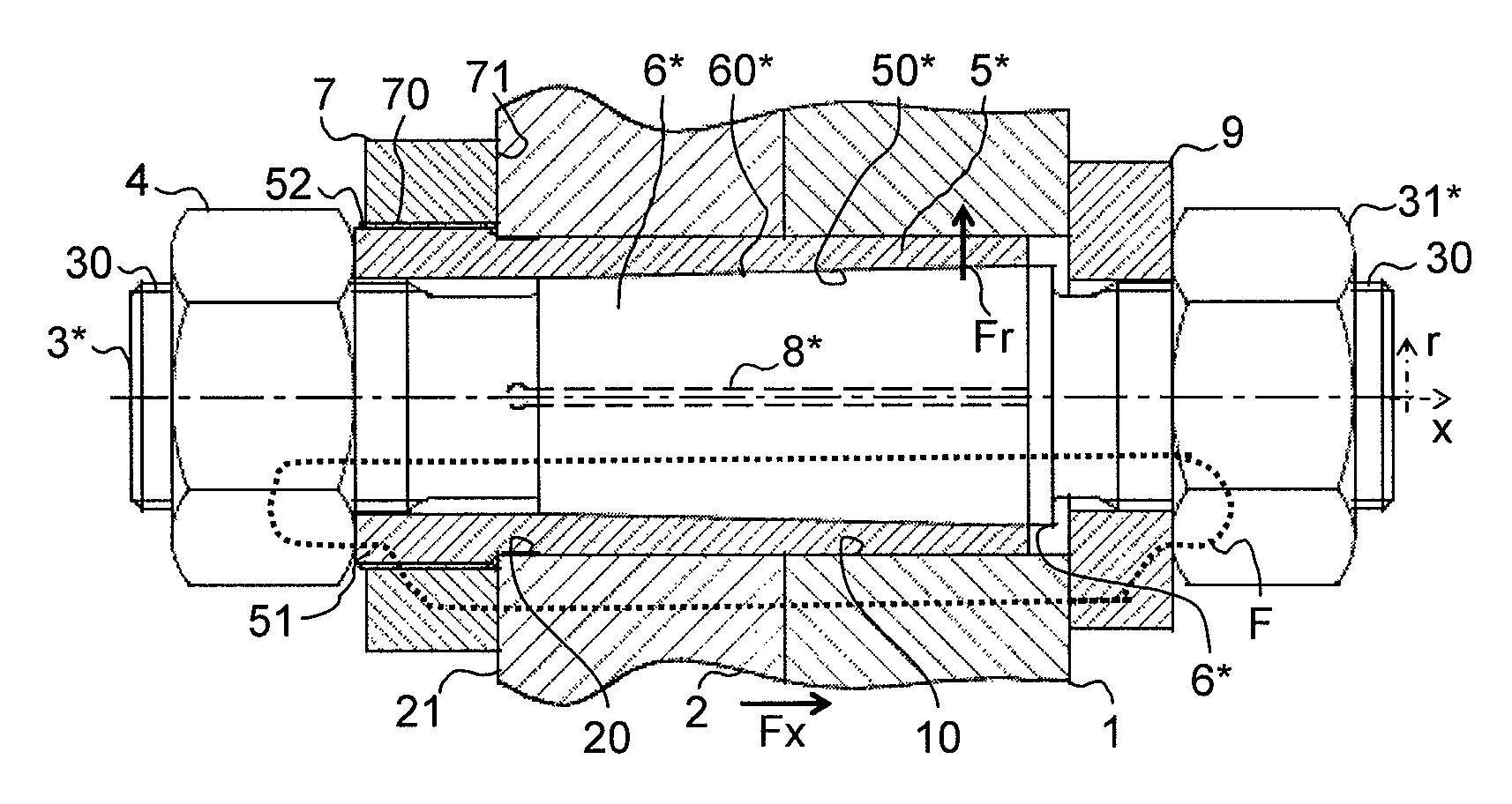
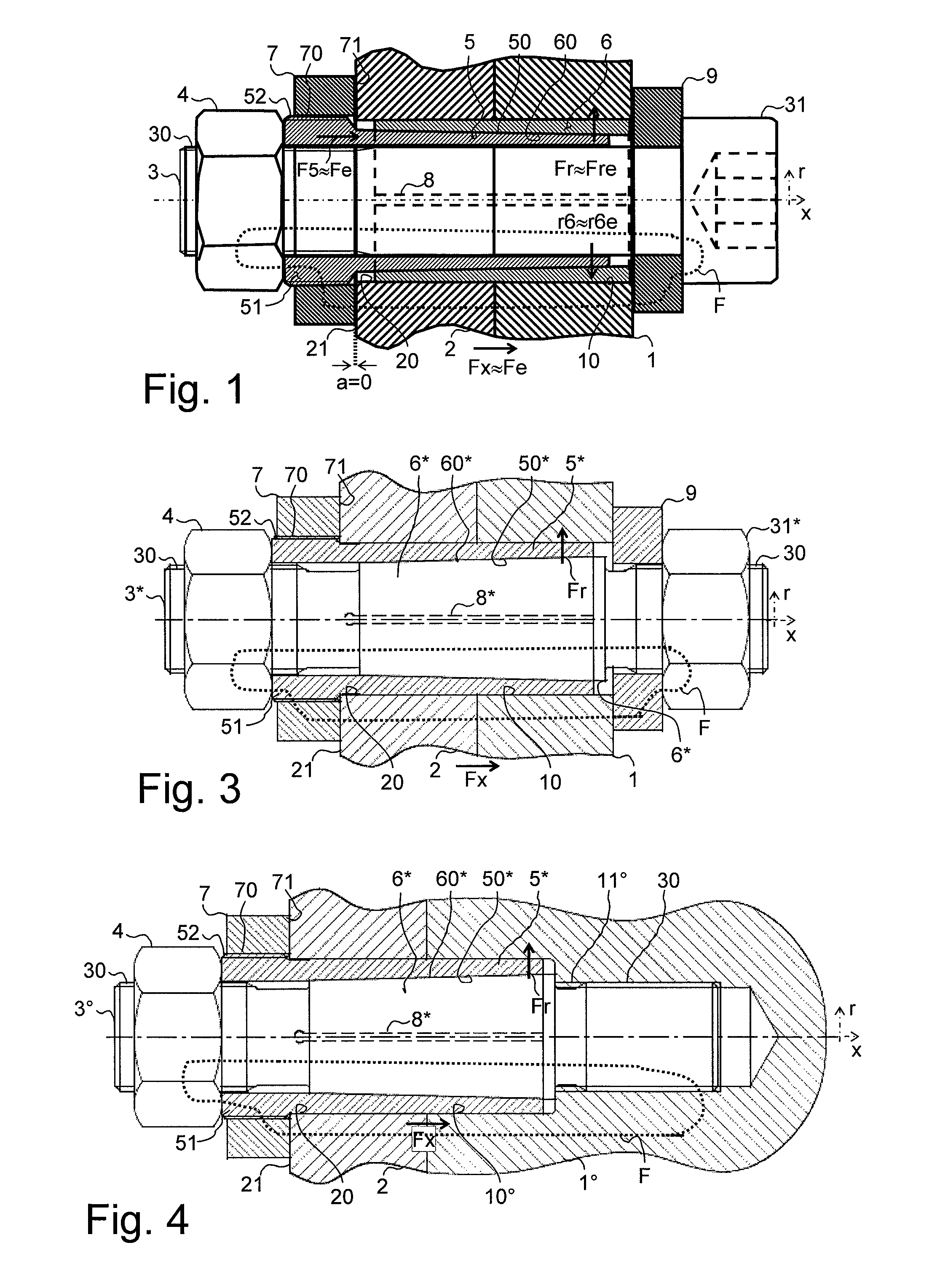
[0083]The second embodiment shown also has a threaded bolt as a bolt 3* instead of a bolt with a screw head, on which a nut 4 can be screwed on both end sections. Thus the nut opposed to the actual clamping nut 4 is arranged as a counter nut 31* serving as a counter bearing and is brought into a defined and thereafter preferably unchanged position prior to the first clamping of the clamping nut 4. Basically, an axial clamping can also be carried out by means of this counter nut 31*.

[0084]FIG. 4 shows a further modified embodiment, in which the first component 1° is formed in a modified manner. Instead of a through opening, the first component 1° has a blind hole, which only extends into the first component 1°.

[0085]In this case, the bolt 3° is screwed into the first component 1° in a fixed position by means of a bolt receiving thread 11°. Optionally, however, the bolt 3° could also be fixedly attached to the first component in a different manner from being screwed in, such as welded...

third embodiment

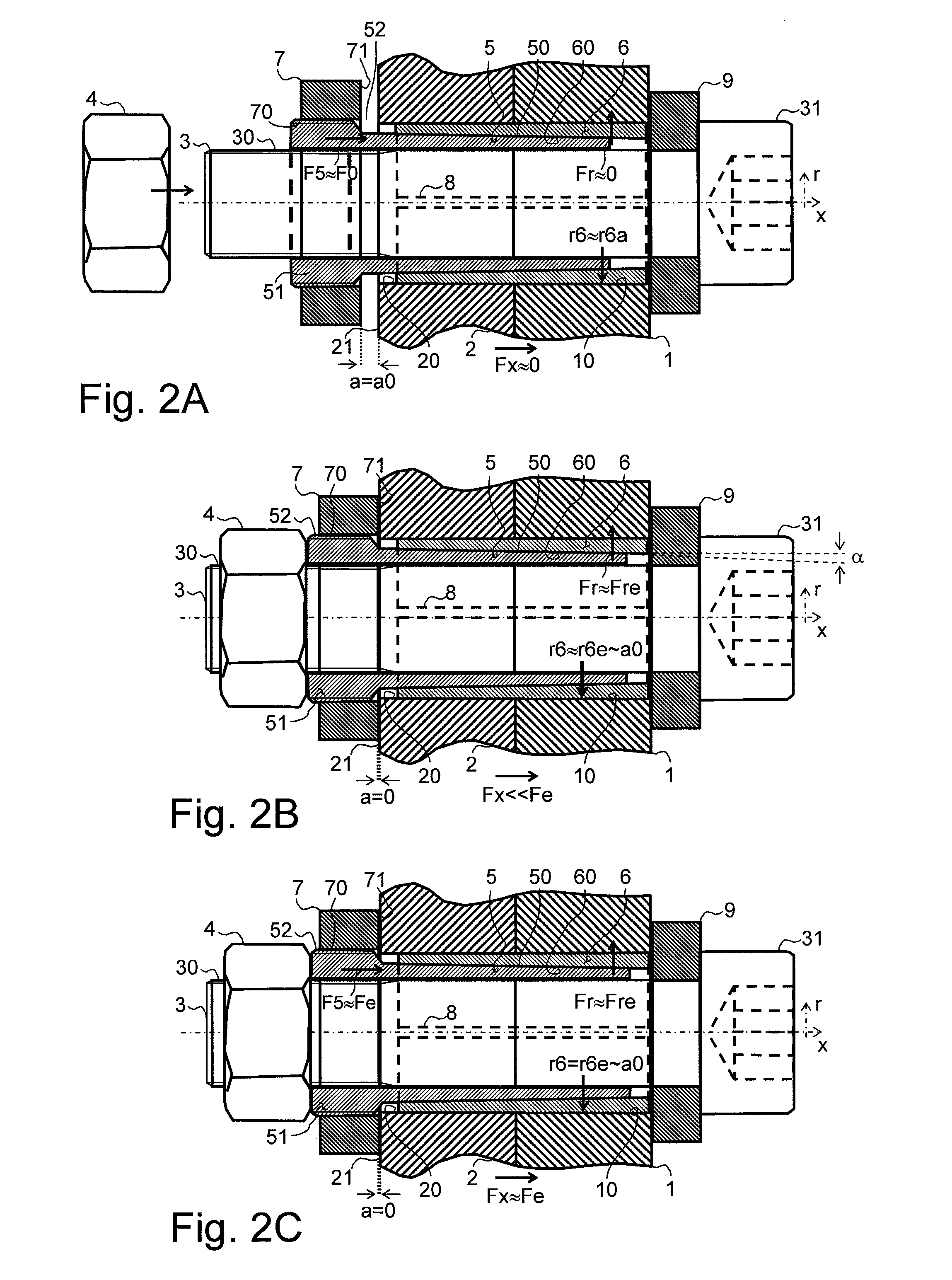
[0086]FIGS. 5A-5F show a method sequence comparable to the method sequence described with reference to FIGS. 2A-2C.

[0087]FIG. 5A shows an early method step, in which the bolt 3° is screwed into the thread 11° of the first component 1°. At the front side of the thread, the bolt 3° extends through the opening 10° of the first component 1° and then through the opening 20 of the second component 2. Herein, a free space is left between the conical outer circumference of the bolt 3° with the outer cone 60* and the inner wall of the two openings 10°, 20.

[0088]In the following, as illustrated in FIG. 5b, the conical clamping element 5* is inserted into this free space to such a point, as permitted by the outer cone 60* of the bolt 3° and the inner cone 50* of the conical clamping element 5* set on it, to compensate manufacturing tolerances and to achieve radial positive engagement. By these means the zero point is defined. Subsequently, the axial locking nut 7 is rotated on the conical cla...


PUM

PropertyMeasurementUnit
Fractionaaaaaaaaaa
Timeaaaaaaaaaa
Forceaaaaaaaaaa

Abstract

A method or arrangement for clamping at least one first and one second component to each other with a connection by force on all sides is disclosed. The connecting arrangement comprises a bolt extending from a first component through a through opening in a second component, a clamping nut which is screwed on the bolt for clamping the components, and a cone pair comprising an inner cone with a split and an outer cone. One part of this cone pair is formed as a conical clamping element, which is arranged and axially moveable for radial clamping on the bolt between the components and the clamping nut. A locking nut is screwed on the conical clamping element and clampable against an abutment surface of the second component to limit moveability of the clamping element.

Description

BACKGROUND[0001]1. Field of the Invention[0002]The invention relates to a connecting arrangement with connection by force on all sides, or to a connecting method.[0003]2. Description of the Related Art[0004]In particular in the construction of heavy machines, large-dimension connections are necessary, which have to be reliably clamped and also released. Screwed, positively connecting connecting elements are used especially in connections loaded by shearing forces. These connecting elements can only be clamped and released with difficulty, however, due to their size.[0005]Considerable manufacturing effort must be encountered with positively connecting connecting elements, which clamp two components to be connected. Bores in the components to be connected must be made with great accuracy and a high surface finish. In actual assembly, the components to be connected must be aligned with each other, which can often only be achieved by repeated mechanical machining of the bore in situ bec...

Claims


Application Information

Patent Timeline
IPC IPC(8): F16B13/06
CPCF16B3/06F16B5/02Y10T29/49826Y10T403/7009Y10T403/645Y10T403/7056Y10T403/75F16B2200/506
Inventor SCHNEIDER, HARALD NORBERT
Owner NORD LOCK AG
Learn More