
Surgical instrument attachment

Active Publication Date: 2013-07-30
DUPUY INT LTD
View PDF12 Cites 1 Cited by
  • Summary
  • Abstract
  • Description
  • Claims
  • Application Information

AI Technical Summary

Benefits of technology

The patent describes an instrument that can be easily attached to a patient's body part by using a brace made of a resilient material that holds the bony parts of the patient. The instrument can be securely attached to the patient by aligning the brace with the position of the bony parts and then sliding the instrument into place. The instrument is designed to resist movement relative to the patient, making it easy to position and secure. The brace can be easily adjusted to compensate for any variations in the position of the bony parts. Overall, the instrument simplifies the process of attaching components to a patient's body, reducing the time and effort required for the procedure.

Problems solved by technology

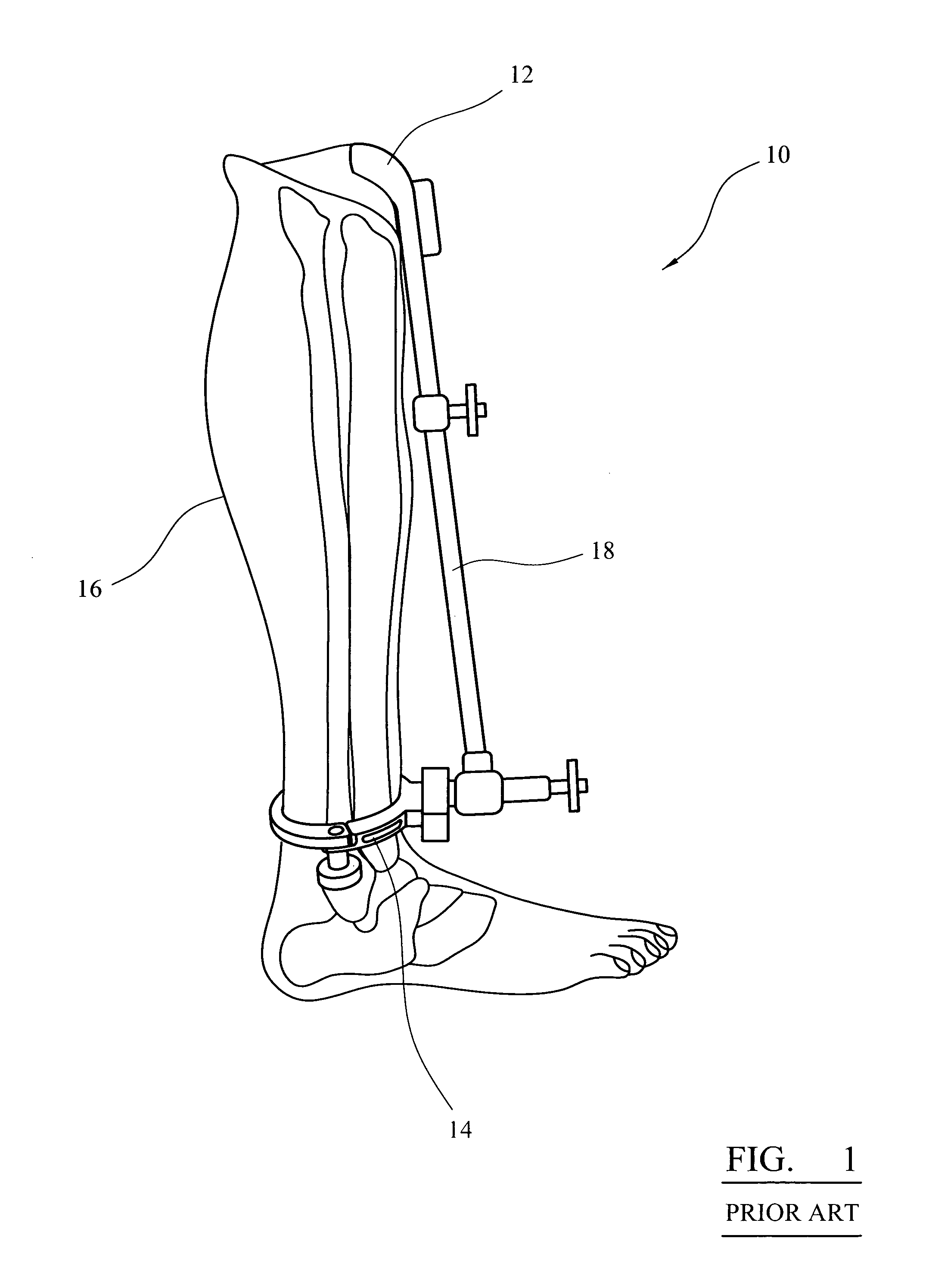
However, the ankle clamp 14 gives rise to a number of problems.
The ankle clamp can give rise to free, as well as accidental, translation and rotation, which will cause the alignment guide to move.
Also, the ankle clamp can be difficult to use in practice as it requires manual manipulation and operation to clamp it around the patient.
Further, during positioning around the patient, a users gloves can become caught in the clamp, which can delay the operation or require the gloves to be damaged and hence need replacing, causing further delays.

Method used


Image

  • Surgical instrument attachment
  • Surgical instrument attachment
  • Surgical instrument attachment

Examples


Embodiment Construction

[0034]Similar items in different Figures share common reference numerals unless indicated otherwise.

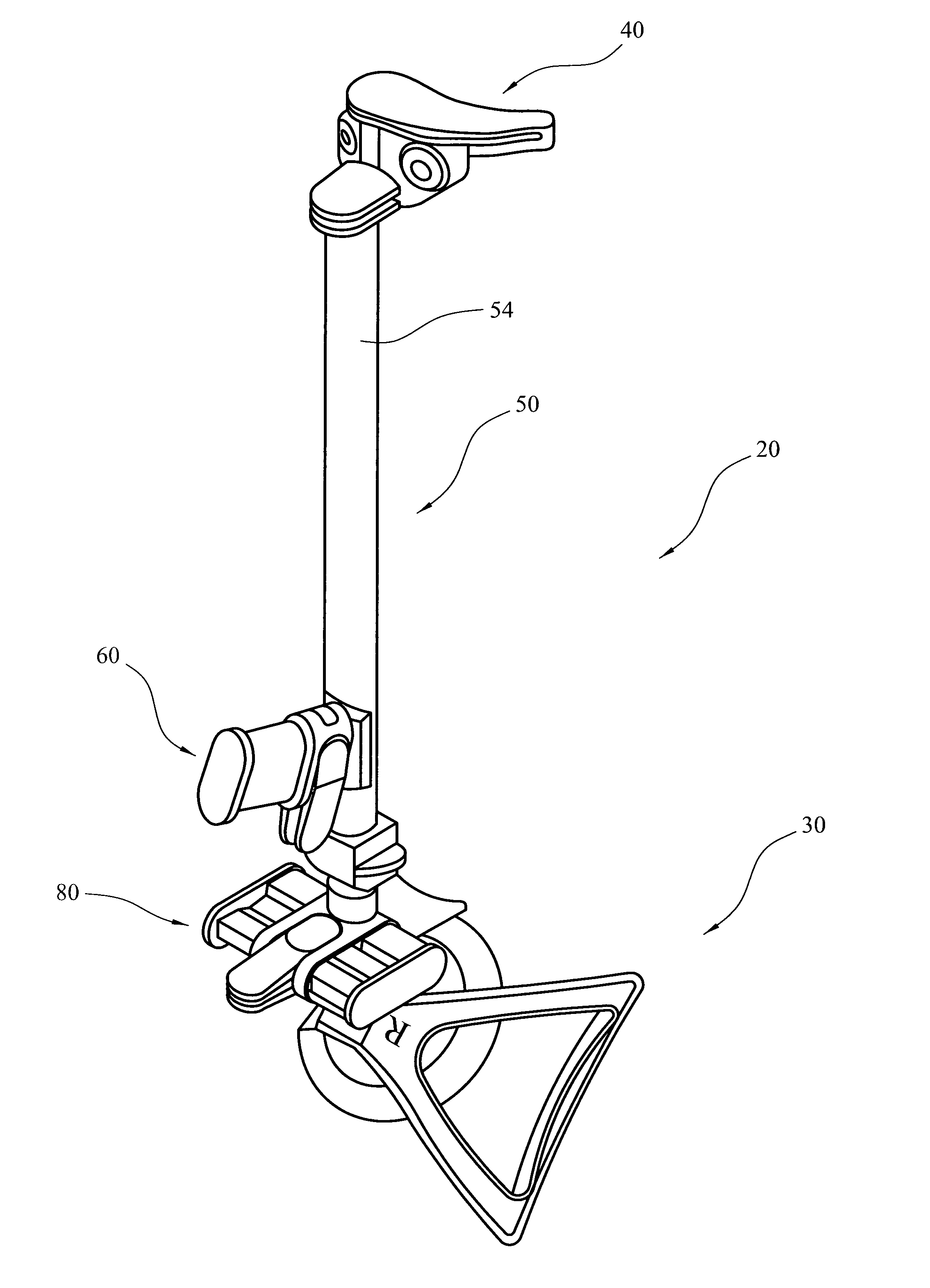
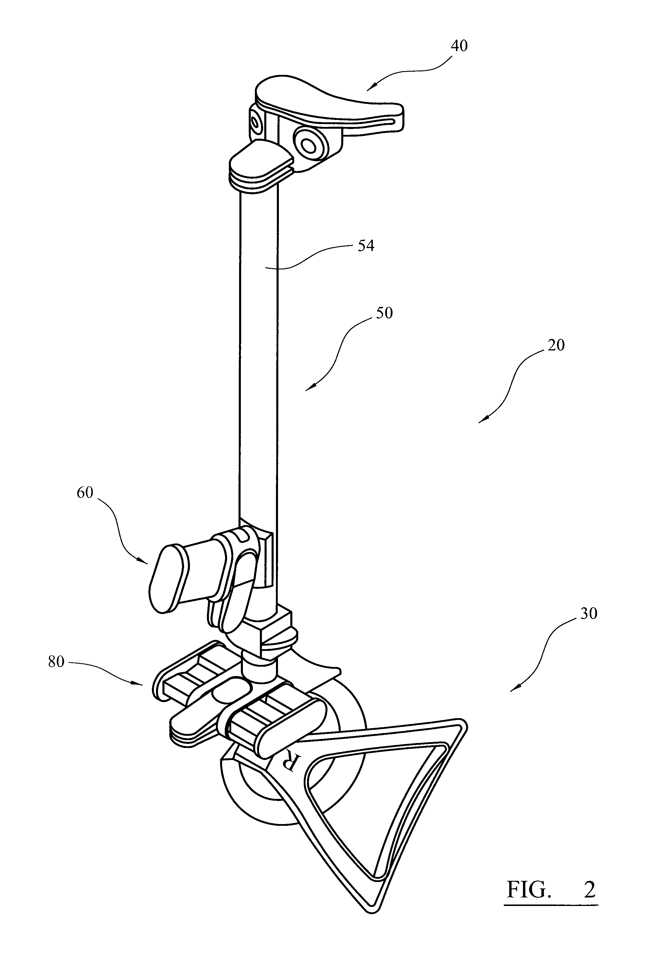
[0035]FIG. 2 shows a perspective view of an instrument 20 according to an embodiment of the present invention. FIG. 3 shows a side view of instrument 20 and FIG. 4 shows a perspective view of the exploded instrument, illustrating its constituent parts.

[0036]The instrument 20 generally includes a brace 30 toward a proximal end of the instrument for attaching the instrument to a patient as will be described in greater detail below. A component 40 is attached to a distal end of the instrument 20 and in the embodiment illustrated the component is in the form of a cutting guide. Instrument 20 also includes a further component 50 through which the cutting guide and brace are attached at respective ends. In the embodiment illustrated, the further component 50 is an external alignment guide. The alignment guide 50 includes a pivot mechanism 60 which allows a first, top portion of the alignmen...


PUM


Abstract

A surgical instrument which can be attached to a patient is described. The instrument includes an alignment guide having a distal end and a proximal end. A brace is attached toward the proximal end of the alignment guide for attaching the instrument to a limb of a patient. The brace comprises a pair of opposed members, each member being shaped to hold a respective bony part of the patient on either side of the patient. At least a part of the brace is made of a resilient material allowing the brace to grip the patient in use.

Description

CROSS REFERENCE TO RELATED APPLICATION[0001]This application is a National Stage 35 U.S.C. 371 of International Patent Application PCT / GB2008 / 003182 filed Sep. 19, 2008.[0002]The present invention relates to a surgical instrument, and in particular to a mechanism for attaching a surgical instrument to a patient.BACKGROUND OF THE INVENTION[0003]Various instruments and devices are used during orthopaedic arthroplasty procedures, such as, e.g., a knee arthroplasty procedure, to assist and guide the positioning of various instruments and devices used during the procedure.[0004]For example, FIG. 1 shows a side view of a prior art external tibial alignment guide 10 attached to the lower leg of a patient which can be used during a knee arthroplasty procedure. The alignment guide 10 is used to position a tibial cutting block 12 against the tibial tubercle to perform a proximal tibial cut. The alignment guide includes an ankle clamp 14 by which the guide 10 is fixed distally to the patient's...

Claims


Application Information

Patent Timeline
IPC IPC(8): A61F5/37
CPCA61B17/157
Inventor KECMAN, MAJASTROUX, LISAVERTERAMO, ALBERTOASHBY, ALAN
Owner DUPUY INT LTD
Learn More