
Motor vehicle braking system having a hydraulically actuated service braking system and an electromechanically actuated braking system

a technology of service braking system and motor vehicle, which is applied in the direction of brake cylinder, anti-theft device, instruments, etc., to achieve the effect of reducing component weight and manufacturing costs

Inactive Publication Date: 2013-07-23
CONTINENTAL TEVES AG & CO OHG
View PDF19 Cites 24 Cited by
  • Summary
  • Abstract
  • Description
  • Claims
  • Application Information

AI Technical Summary

Benefits of technology

[0007]By contrast, an aspect of the invention makes available a motor vehicle brake system and an operating method which eliminate the disadvantages of the prior art and make it possible to design all the components of a motor vehicle to be durable without excessive dimensioning while retaining the same fundamental reliability, and thereby to contribute to reducing component weight and manufacturing costs.
[0011]A fundamental service brake function of an integrated brake caliper is in no way impaired by the measure described. Rather, use is made of the consideration that, with the vehicle at standstill on an incline (rising or falling gradient) which is measured or assumed as given, significantly lower hydraulic pressures in the brake system or in the integrated brake calipers are sufficient, depending on demand, to achieve a defined holding of a vehicle than can be generated by a vehicle driver by completely spontaneous actuation of a brake pedal / actuation of the service brake function, so that such spontaneous, excessive brake actuation is implemented in an electronically regulated, that is, modified manner, and is conditioned in such a way that the system components are protected from unnecessary overloading while retaining complete system availability with full functionality.
[0012]An aspect of the invention makes it possible to increase the durability of the components of the electromechanically actuatable brake system by predictively preventing certain cases of actuation of a load spectrum which have increased damage potential. This can be effected by intelligent activation of components of an HECU in combination with pressure limiting or pressure reduction. The invention therefore serves and makes possible, in particular, a greatly improved, networked activation system between an electromechanically actuatable parking brake system and an ESP service brake system which is present in any case, by adjusting to one another and regulating the common resources, energy sources and actuators and activating them only to an extent which is strictly necessary in order to achieve the desired application force result.

Problems solved by technology

Known systems, devices and methods, in combination with so-called integrated brake calipers, suffer from the disadvantage that an electromechanical drive and transmission system of the actuator and, above all, the brake caliper housing and the brake caliper bridge, must in principle be designed to be overdimensioned mechanically, that is, to have considerably higher power capacity than is strictly necessary, in order to be able to reliably withstand alternating stresses in the transfer process.

Method used


Image

  • Motor vehicle braking system having a hydraulically actuated service braking system and an electromechanically actuated braking system
  • Motor vehicle braking system having a hydraulically actuated service braking system and an electromechanically actuated braking system
  • Motor vehicle braking system having a hydraulically actuated service braking system and an electromechanically actuated braking system

Examples


Embodiment Construction

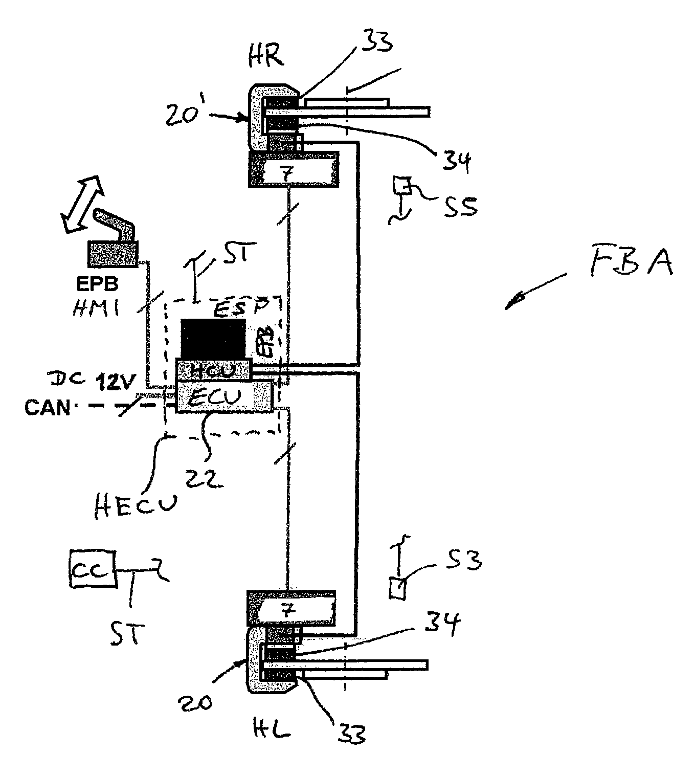
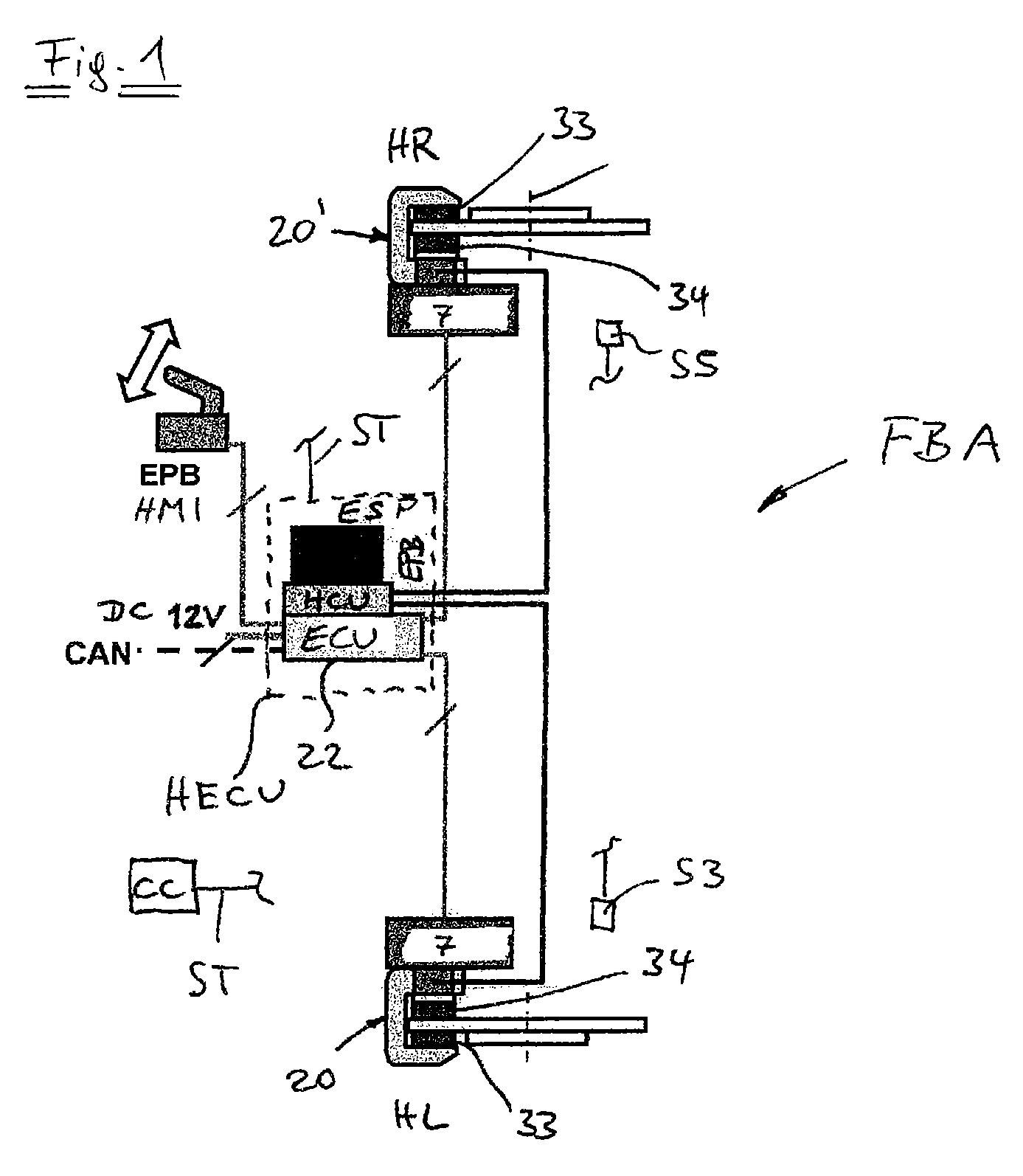
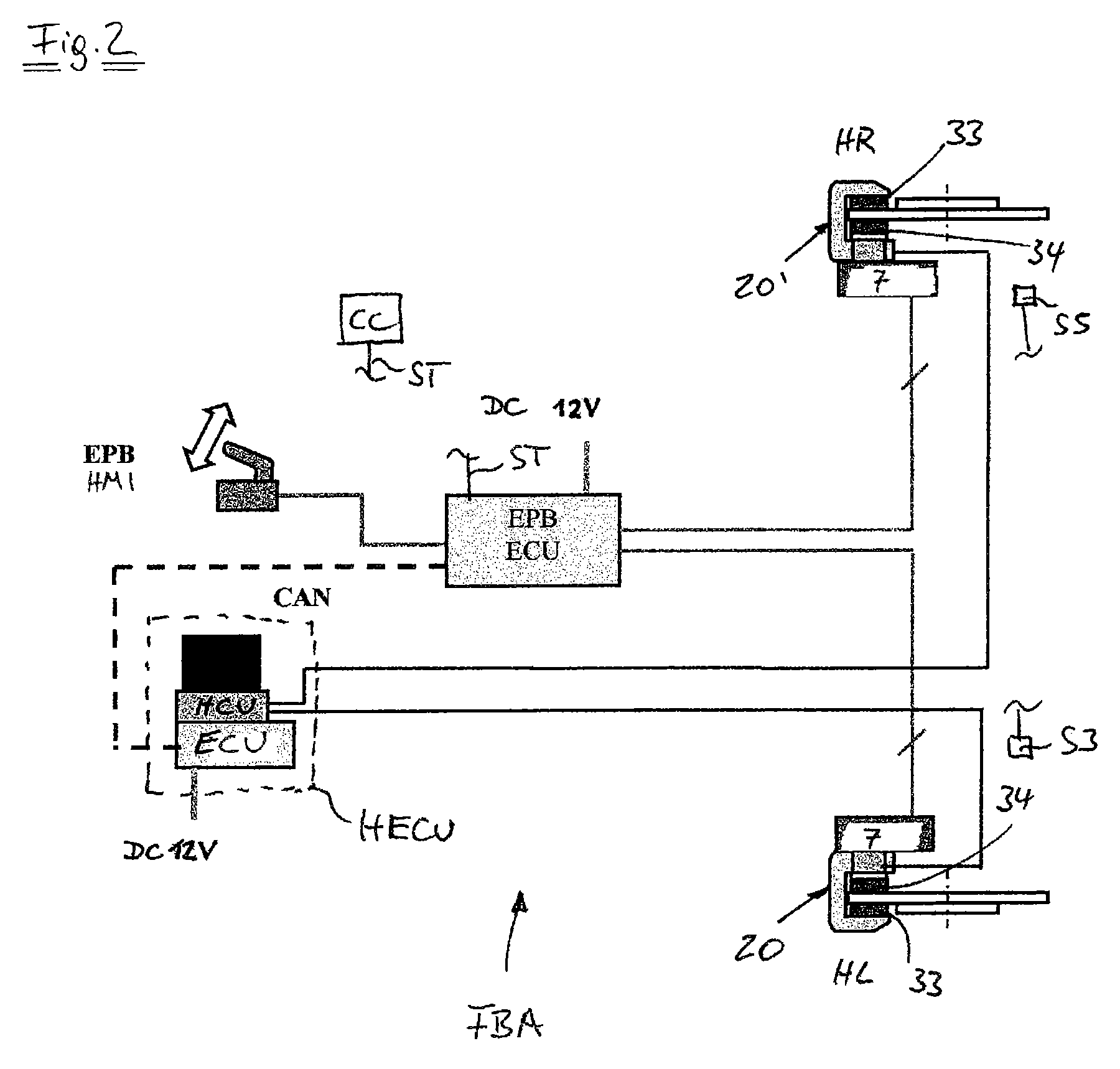
[0021]A vehicle brake comprises, on the one hand, a hydraulically actuatable service brake function and, on the other, an electromechanically actuatable brake function which is designed primarily as a parking brake function. As shown in FIG. 4, the vehicle brake is in the form of a floating-caliper disk brake. An electromechanical actuator 7 including an electric motor 7a serves to execute an electromechanical braking function. The actuator 7 includes a multi-stage, in particular two-stage, transmission 1, sensors S1-Sx and an electronic control unit 22 (ECU (EPB)). The above-mentioned vehicle brake further comprises a brake housing or brake caliper 20, 20′ which extends around the outer edge of a brake disk (not shown), and two brake pads 33, 34 arranged on each side of the brake disk. The brake caliper 20 has on its inner side a brake cylinder 9 which receives an axially displaceable brake piston 5. In order to perform service brake operations, brake fluid can be supplied to the o...


PUM


Abstract

The invention relates to a motor vehicle brake system having a hydraulically actuatable service brake system and an electromechanically actuatable brake system, including an operating element HMI, in particular for activating a parking brake function, an electronic control device (EPB-ECU) for activating an electromechanical actuator of the electromechanically actuatable brake system, and an electrohydraulic control unit (HECU) associated with a service brake and serving to control or regulate hydraulically implemented service brake functions, driving stability functions and / or braking assistance functions. It is an aim of the invention to contribute to reducing the stress on parts or components of the brake system. It is proposed that an electronically controlled hydraulic pressure conditioning process is carried out in integrated brake calipers after hydraulic actuation of the brake, it being further provided that the electromechanical brake system generates additional application forces only after the hydraulic pressure conditioning process.

Description

CROSS REFERENCE TO RELATED APPLICATIONS[0001]This application is the U.S. National Phase Application of PCT International Application No PCT / EP2010 / 058644, filed Jun. 18, 2010, which claims priority to German Patent Application No. 10 2009 027 035.3, filed Jun. 18, 2009, the contents of such application being incorporated by reference herein.FIELD OF THE INVENTION[0002]The present invention relates to a motor vehicle brake system having the features of the preamble of claim 1. The combination of features, as a brake system having an electromechanically implemented parking brake function, is known in principle.[0003]The invention further relates to an associated operating method for the motor vehicle brake system.BACKGROUND OF THE INVENTION[0004]Known from EP 0 825 081 B1 which is incorporated herein is a motor vehicle having a driving stability function (ESP) and a hydraulic pressure generator in the form of a pump having an electromechanical adjusting unit for an actuator, a transf...

Claims


Application Information

Patent Timeline
Patent Type & Authority Patents(United States)
IPC IPC(8): B60T17/08
CPCB60T7/107B60T8/32B60T8/885B60T13/588B60T13/741B60T17/221F16D65/18B60T2270/413F16D2121/02F16D2121/24F16D2123/00F16D2125/40F16D2125/48B60T7/10B60T13/74B60W10/22F16D65/14
Inventor SCHNEIDER, HEINZ-ANTONBALZ, JURGEN
Owner CONTINENTAL TEVES AG & CO OHG
Learn More