Lamp with heat sink and lamp cover mounted on the heat sink

a technology of heat sink and lamp cover, which is applied in the field of lamps, can solve the problems of time-consuming and inconvenient assembly of lamps

Inactive Publication Date: 2013-07-23
HON HAI PRECISION IND CO LTD
View PDF5 Cites 1 Cited by
  • Summary
  • Abstract
  • Description
  • Claims
  • Application Information

AI Technical Summary

Benefits of technology

[0017]In assembly, the lamp cover 17 is placed over the first face 141 of the main body 14 of the heat sink 13 with the connecting portion 172 of the lamp cover 17 aimed at the opening 158 of the heat sink 13. The lamp cover 17 is then pushed downwardly to cause the connecting portion 172 to move downwardly along the guiding surfaces 154 of the hooks 153 whereby the hooks 153 are outwardly pushed and the opening 158 of the heat sink 13 is enlarged. The tapered guiding surfaces 154 of the hooks 153 thus guide the connecting portion 172 to slide into the engaging groove 157 of the heat sink 13. Once the connecting portion 172 has entered the engaging groove 157, the hooks 153 elastically restore back to their original state. The securing surfaces 155 of the hooks 153 abut against the connecting portion 172 of the lamp cover 17. The clamping portions 151 of the heat sink 13 prevent the connecting portion 172 of the lamp cover 17 from escaping from the engaging groove 157. The connecting portion 172 of the lamp cover 17 is engaged in the engaging groove 157 and abuts a periphery portion of the first surface 141 of the main body 14 of the heat sink 13. The clamping portions 151 of the heat sink 13 surround the lamp cover 17 and fix the connecting portion 172 of the lamp cover 17 onto the top side of the heat sink 13. Therefore, the lamp cover 17 is easily and firmly fixed on the heat sink 13.

Problems solved by technology

However, the screws must be individually threaded into the lamp cover and the heat sink one by one; thus, assembly of the lamp is inconvenient and time-consuming.

Method used


Image

  • Lamp with heat sink and lamp cover mounted on the heat sink
  • Lamp with heat sink and lamp cover mounted on the heat sink
  • Lamp with heat sink and lamp cover mounted on the heat sink

Examples


Embodiment Construction

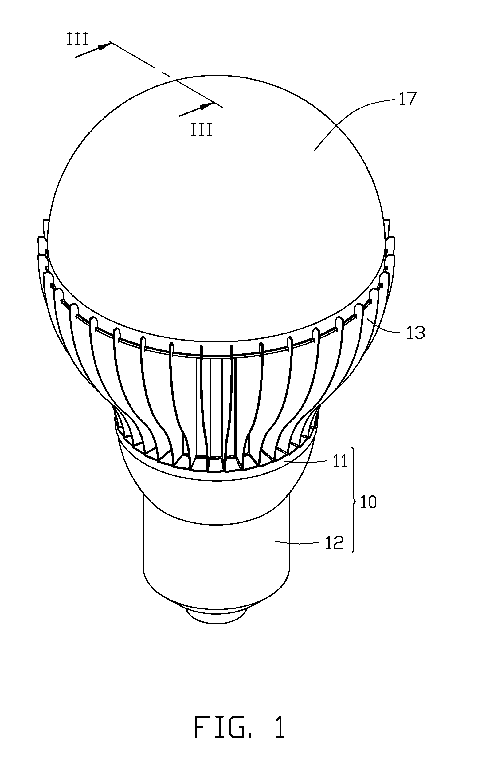
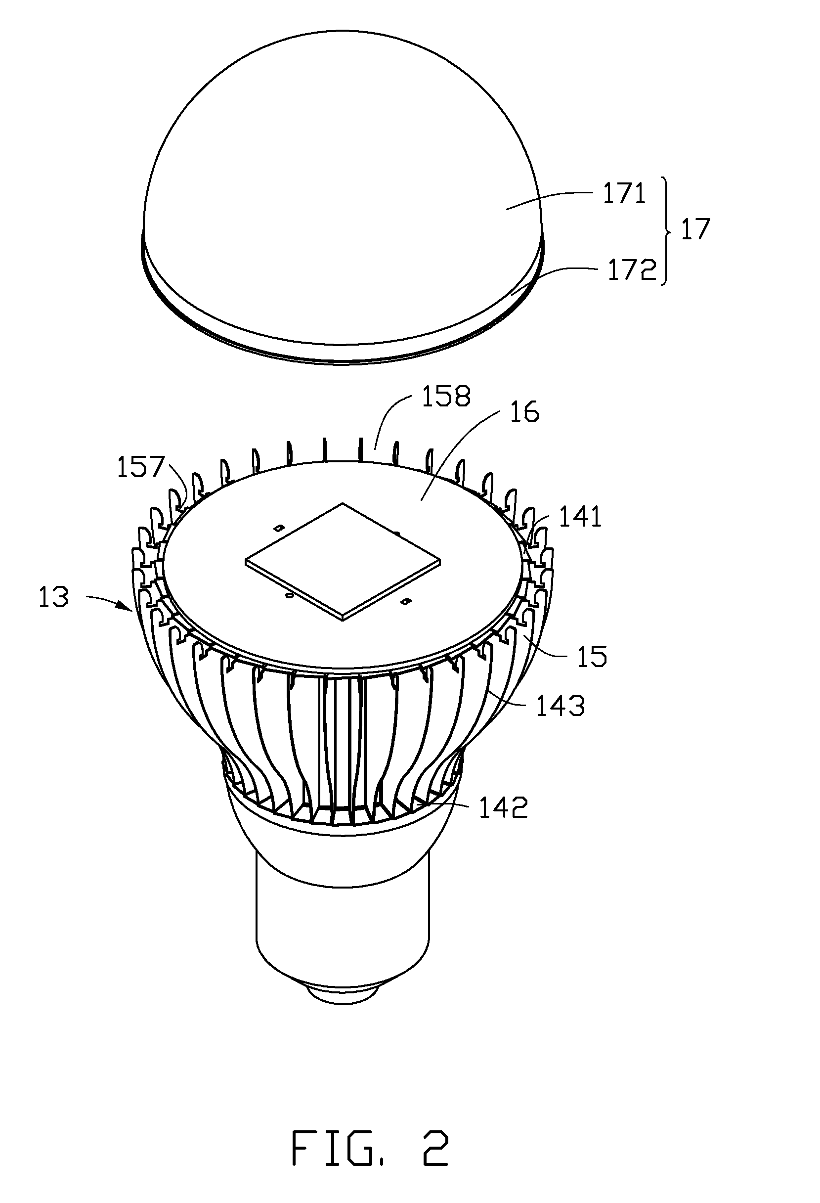
[0010]As shown in FIGS. 1-3, a lamp in accordance with an embodiment of the present disclosure includes a lamp holder 10, a heat sink 13 connected with the lamp holder 10, a light source 16 mounted on the heat sink 13, and a lamp cover 17 mounted on the heat sink 13 and covering the light source 16.

[0011]The lamp holder 10 includes a securing portion 11 and an electrical connector 12. The electrical connector 12 is secured to one end (i.e., bottom end) of the securing portion 11, and is configured for connecting a power source (not shown) which can supply an electric power to the lamp. The other end (i.e., top end) of the securing portion 11 securely connects with the heat sink 13. The electrical connector 12 can be directly inserted into a standard socket for a conventional incandescent bulb or fluorescent lamp which is electrically connected with the power source, such that the lamp in accordance with the present disclosure can replace the conventional incandescent bulb or compact...


PUM

PropertyMeasurementUnit
electrical poweraaaaaaaaaa
electric poweraaaaaaaaaa
translucentaaaaaaaaaa

Abstract

A lamp includes a heat sink and a lamp cover mounted on the heat sink. The lamp cover includes a connecting portion. The heat sink includes a plurality of clamping portions. The plurality of clamping portions surrounds the lamp cover and is spaced apart from each other along a circumferential direction. The plurality of clamping portions each defines a recess facing the lamp cover. The recesses communicate with each other along the circumferential direction whereby an annular engaging groove is defined in the heat sink by the recesses. The connecting portion is engaged in the engaging groove whereby the lamp cover is connected with the heat sink.

Description

BACKGROUND[0001]1. Technical Field[0002]The present disclosure relates generally to lamps, and more particularly to a lamp having a lamp cover and a heat sink which can be easily assembled.[0003]2. Description of Related Art[0004]Usually, a lamp has a lamp cover and a heat sink detachably connected with the lamp cover via a plurality of screws. However, the screws must be individually threaded into the lamp cover and the heat sink one by one; thus, assembly of the lamp is inconvenient and time-consuming.[0005]What is needed therefore is a lamp which can overcome the above limitations.BRIEF DESCRIPTION OF THE DRAWINGS[0006]Many aspects of the present embodiment can be better understood with reference to the following drawings. The components in the drawings are not necessarily drawn to scale, the emphasis instead being placed upon clearly illustrating the principles of the present embodiment. Moreover, in the drawings, like reference numerals designate corresponding parts throughout ...

Claims


Application Information

Patent Timeline
Patent Type & Authority Patents(United States)
IPC IPC(8): H01J61/52
CPCF21K9/135F21V3/0445F21V17/164F21V29/77F21V29/004F21Y2101/02F21Y2105/001F21Y2105/10F21K9/232F21Y2115/10F21V3/0625F21V29/773
Inventor HUNG, JUI-WENHWANG, CHING-BAI
Owner HON HAI PRECISION IND CO LTD
Why Eureka
Try Eureka