Dual-bearing reel

a reel and dual-bearing technology, applied in the field of fishing reels, can solve the problems of imbalance between the clutch operating member and the side plate, poor appearance, and inability to adjust the position of the clutch operating member, so as to prevent the gap between the left and right sid

Active Publication Date: 2019-12-12
SHIMANO COMPONENTS MALAYSIA
View PDF1 Cites 1 Cited by
  • Summary
  • Abstract
  • Description
  • Claims
  • Application Information

AI Technical Summary

Benefits of technology

[0011]Preferably, the clutch operating member is slidable with respect to the second side plate in the up-down direction. In this case, even if the gap between the clutch operating member and both side plates of the reel body is reduced and the clutch operating member is biased due to a dimensional error, the clutch operating member can be prevented from strongly coming into contact with one of the side plates. In addition, it is possible to prevent the left and right side gaps between the clutch operating member and the both side plates from becoming imbalanced.
[0012]Preferably, the dual-bearing reel further includes a barrier portion disposed on one of the clutch operating member and the reel body for preventing a fishing line from entering the gap between the clutch operating member and the first side plate of the reel body. In this case, the clutch operating member can be disposed at an appropriate position with respect to the first side plate of the reel body, and entanglement of the fishing line between the clutch operating member and the reel body can be prevented by the barrier portion.

Problems solved by technology

In a conventional clutch operating member, however, when fixing the clutch operating member to the clutch plate with screws, the position to fix the clutch operating member cannot be adjusted.
For this reason, when the gap between the side plates of the reel body is reduced, the clutch operating member is biased due to a dimensional error, whereby the clutch operation member is likely to strongly come into contact with one of the side plates.
Further, there is a possibility that the gap between the clutch operating member and the side plates becomes imbalanced on the left and right sides, and the appearance is poor in this case.

Method used


Image

  • Dual-bearing reel
  • Dual-bearing reel
  • Dual-bearing reel

Examples


Embodiment Construction

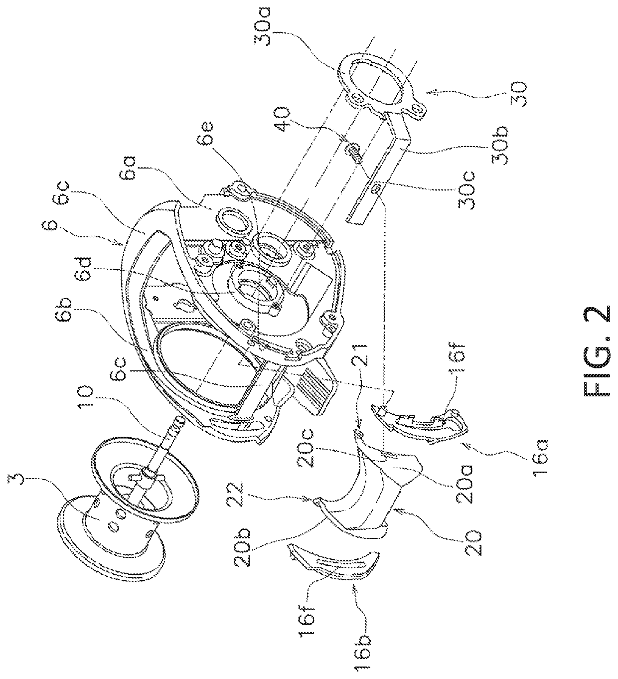
[0021]In the following descriptions, when fishing, the direction in which a fishing line is unreeled (cast) is referred to as the “front” and the opposite direction is referred to as the “rear”. Further, the term “left and right” indicates the left and right side when a dual-bearing reel 100 is viewed from the rear. Also, the term “axial direction” indicates an extending direction of a spool shaft 10 (refer to FIG. 2).

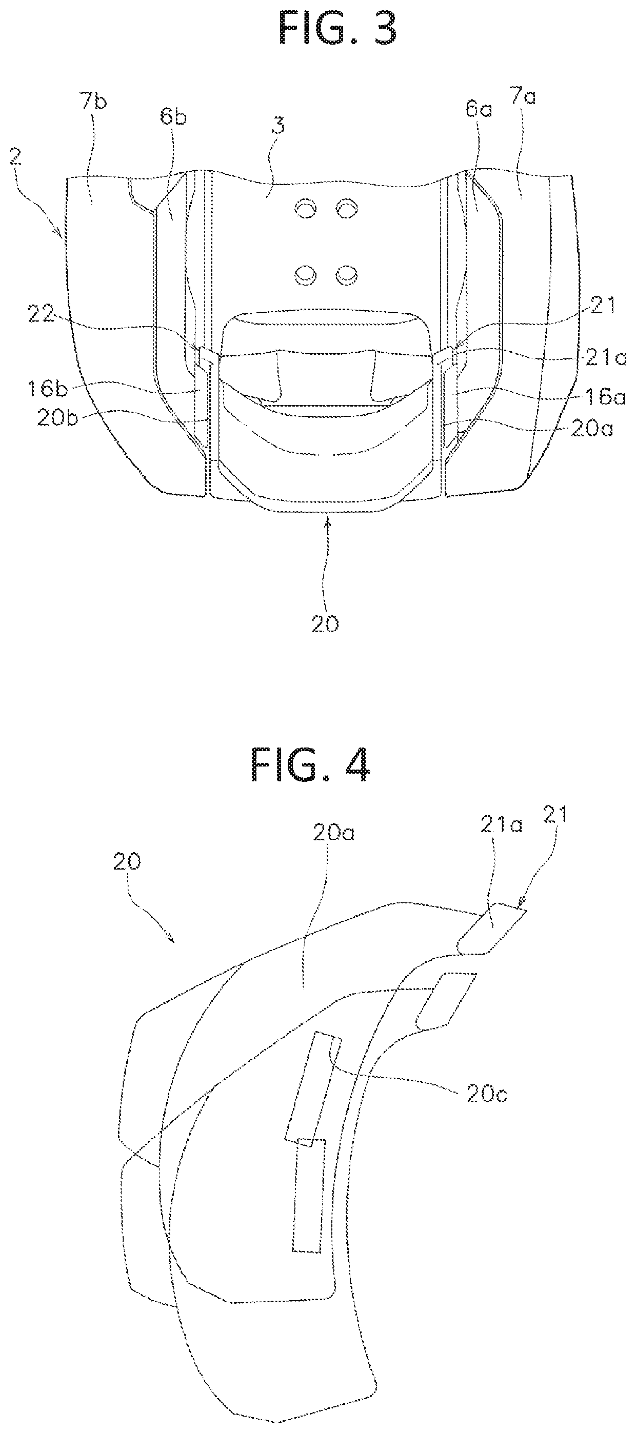
[0022]The dual-bearing reel 100 adopting an embodiment of the present disclosure is configured to release a fishing line forward. As shown in FIGS. 1 to 3, the dual-bearing reel 100 includes a reel body 2, a spool 3, a handle 4, a clutch operating member 20, a clutch plate 30, and a fixing member 40.

[0023]As shown in FIGS. 1 and 2, the reel body 2 includes a frame 6, a first side cover 7a, and a second side cover 7b. The frame 6 includes a first sideplate 6a, a second side plate 6b, and a plurality of coupling portions 6c.

[0024]The first side plate 6a is disposed on t...


PUM


Abstract

A dual-bearing reel is disclosed. The dual-bearing reel is configured to release a fishing line forward and includes a reel body, a clutch operating member, a clutch plate, and a fixing member. The clutch operating member is supported on the reel body movably in the up-down direction. The clutch plate is rotatably supported by the reel body and includes an extending portion extending in the axial direction and fixed to the clutch operating member to be integrally movable therewith, and a through hole in the extending portion. The fixing member fixes the clutch operating member to the extending portion via the through hole of the clutch plate. The through hole has a clearance with respect to the fixing member in the axial direction.

Description

CROSS-REFERENCE TO RELATED APPLICATIONS[0001]This application claims priority to Japanese Patent Application No. 2018-110995, filed Jun. 11, 2018. The contents of that application are incorporated by reference herein in their entirety.BACKGROUNDTechnical Field[0002]The present disclosure relates to a fishing reel, in particular, to a dual-bearing reel capable of releasing a fishing line forward.Background Information[0003]A dual-bearing reel includes a clutch operating member for switching the transmitting and blocking of the rotational force from a handle to a spool. The clutch operating member is coupled to a clutch control mechanism via a clutch plate. Further, the clutch operating member is movable in the up-down direction at the rear of a reel body and is disposed with a slight gap between both side plates of the reel body (refer to Japanese Laid-open Patent Application Publication No. 2013-153659).BRIEF SUMMARY[0004]The smaller the gap between the clutch operating member and b...

Claims


Application Information

Patent Timeline
Patent Type & Authority Applications(United States)
IPC IPC(8): A01K89/015
CPCA01K89/01921A01K89/0186A01K89/01931A01K89/033A01K89/015A01K89/0155
Inventor BIN AHMAD, ABU SUPIANBIN ISMAIL, MOHD SYAMSUL JOHARYBIN SABTU, BAIHAKIBIN MUSTAPHA, MUHD SYUKRI NAZRY
Owner SHIMANO COMPONENTS MALAYSIA
Why Eureka
Try Eureka