Assessment and calibration of a crimp tool equipped with ultrasonic analysis features

a technology of ultrasonic analysis and crimping tool, which is applied in the direction of material analysis using wave/particle radiation, instruments, specific gravity measurement, etc., can solve the problem of gradual fallout of toleran

Inactive Publication Date: 2013-07-23
NASA
View PDF2 Cites 6 Cited by
  • Summary
  • Abstract
  • Description
  • Claims
  • Application Information

AI Technical Summary

Problems solved by technology

As the UECT is repeatedly used, physical wear and use may affect alignment, causing the UECT to gradually fall out of tolerance.

Method used


Image

  • Assessment and calibration of a crimp tool equipped with ultrasonic analysis features
  • Assessment and calibration of a crimp tool equipped with ultrasonic analysis features
  • Assessment and calibration of a crimp tool equipped with ultrasonic analysis features

Examples


Embodiment Construction

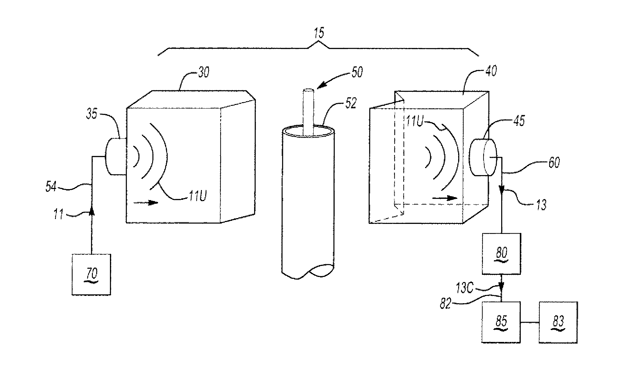
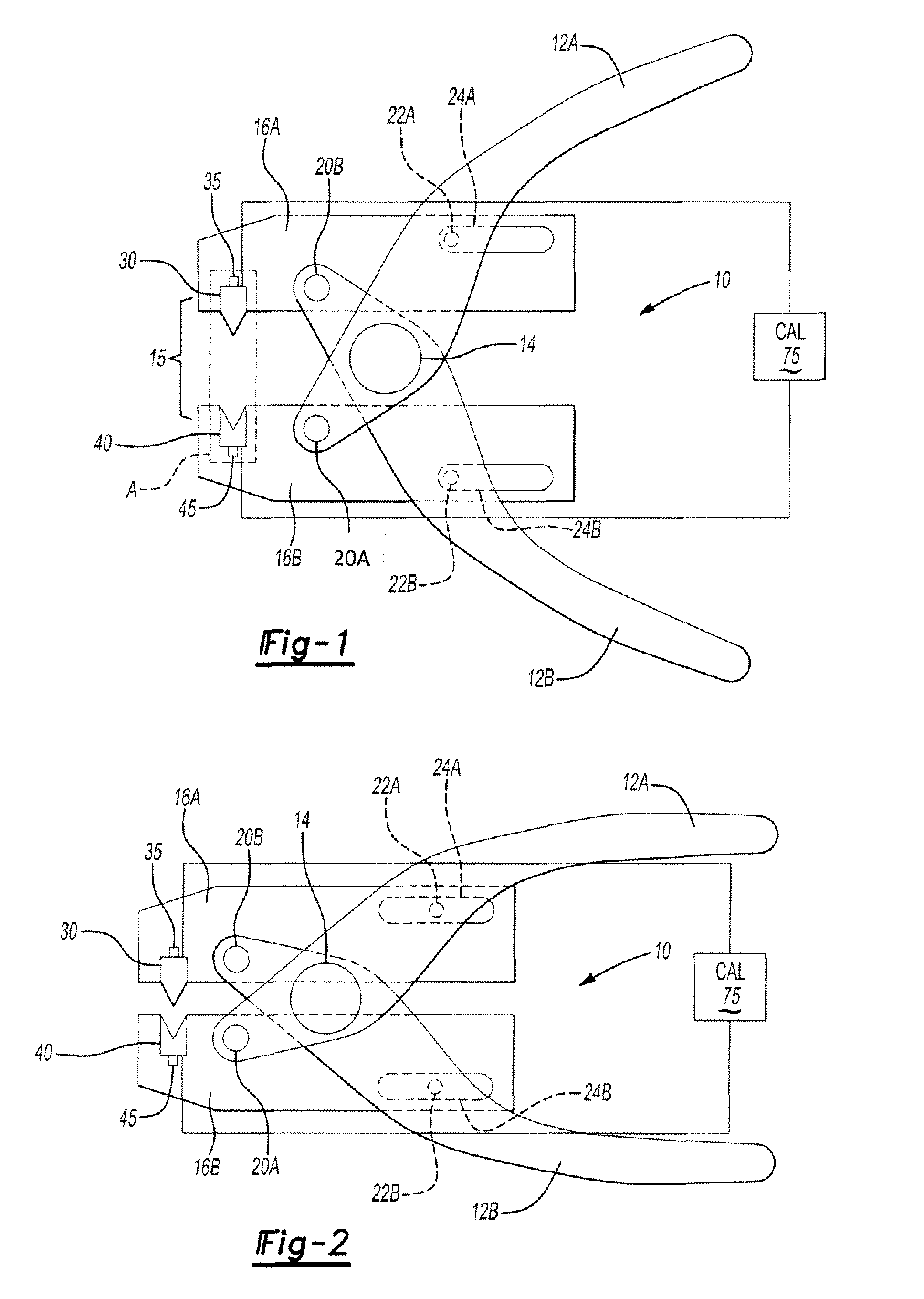
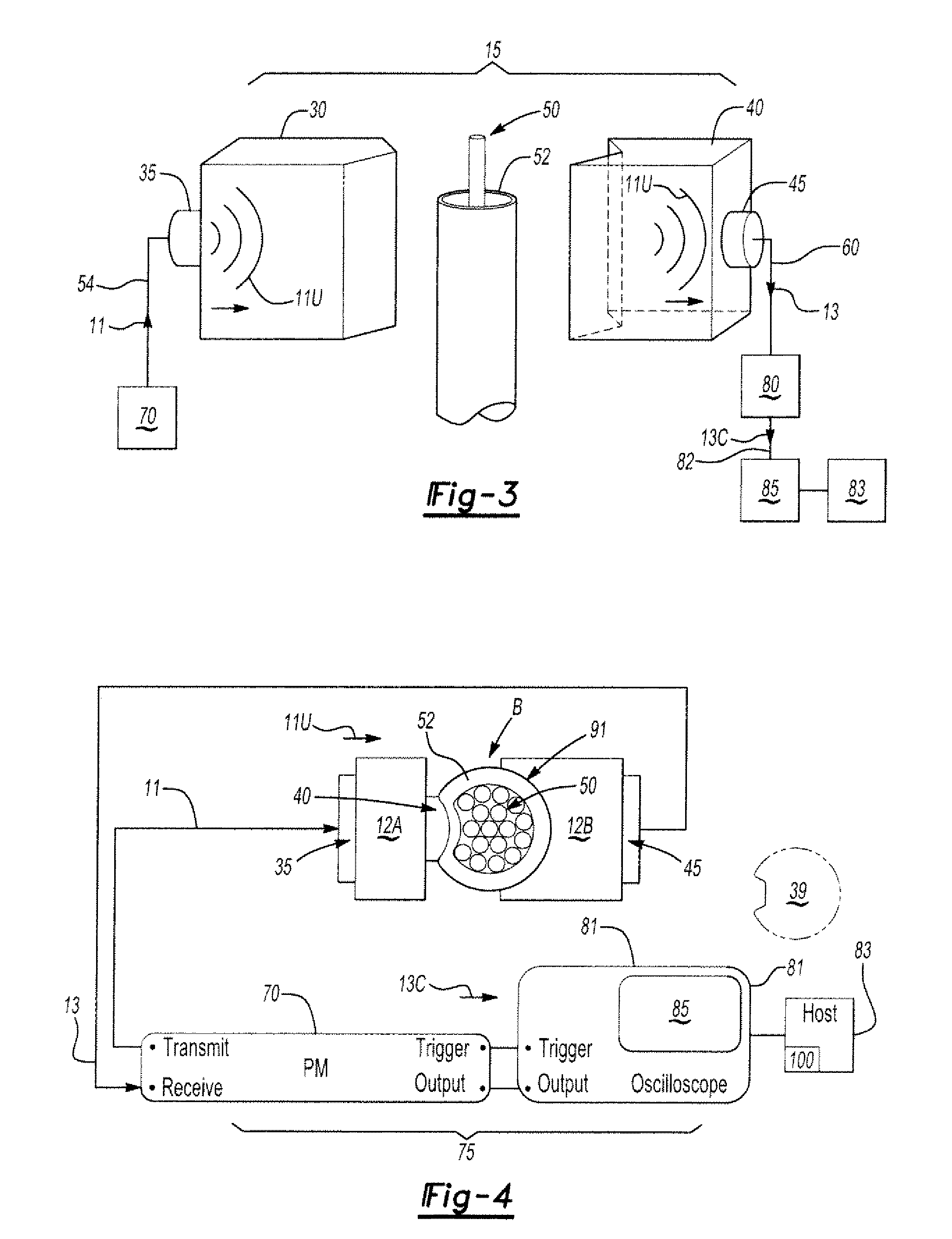
[0018]Referring to the drawings wherein like reference numbers represent like components throughout the several figures, FIGS. 1 and 2 show an ultrasonically-equipped crimp tool or UECT 10 in an open or uncompressed state (FIG. 1) and a closed or compressed state (FIG. 2). A calibration system (CAL) 75 is electrically connected to the UECT 10, and is adapted for calibrating the UECT and an ultrasonic signal passed through a region of a crimp formed with respect to a deformable body, as explained below with reference to FIGS. 4-6.

[0019]The shown UECT 10 includes a pair of handles 12A and 12B which are each connected to, and allowed to rotate about, a coaxial pivot 14. The UECT 10 also includes jaws 16A and 16B, which are positioned opposite one another. Handle 12A is pivotally attached to the jaw 1613 at a pivot 20A, and handle 1213 is likewise pivotally attached to jaw 16A at a pivot 20B. Guide pins 22A and 2213 are secured on the handles 12A and 1213, respectively. Jaws 16A and 16B...


PUM

PropertyMeasurementUnit
frequencyaaaaaaaaaa
rise timeaaaaaaaaaa
frequenciesaaaaaaaaaa

Abstract

A method is provided for calibrating ultrasonic signals passed through a crimp formed with respect to a deformable body via an ultrasonically-equipped crimp tool (UECT). The UECT verifies a crimp quality using the ultrasonic signals. The method includes forming the crimp, transmitting a first signal, e.g., a pulse, to a first transducer of the UECT, and converting the first signal, using the first transducer, into a second signal which defines an ultrasonic pulse. This pulse is transmitted through the UECT into the crimp. A second transducer converts the second signal into a third signal, which may be further conditioned, and the ultrasonic signals are calibrated using the third signal or its conditioned variant. An apparatus for calibrating the ultrasonic signals includes a pulse module (PM) electrically connected to the first and second transducers, and an oscilloscope or display electrically connected to the PM for analyzing an electrical output signal therefrom.

Description

ORIGIN OF THE INVENTION[0001]The invention described herein was made by employees of the United States Government and may be manufactured and used by or for the Government for governmental purposes without payment of any royalties thereon or therefor.TECHNICAL FIELD[0002]The present invention relates to a method and an apparatus for calibrating a crimping tool having transducers adapted for determining, via ultrasonic signal generation and processing, the quality of a resultant crimped joint.BACKGROUND OF THE INVENTION[0003]Crimping is a cold-working process used to join mutually-deformable objects, at least one of which is typically constructed of metal or another malleable material. For example, in forming a crimped electrical connection, a wire may be deformed with respect to a barrel or a ferrule in order to form a crimped joint, hereinafter referred to as a crimp for simplicity. Crimping tools are the devices most typically used to compress a bundle of wires together, and to co...

Claims


Application Information

Patent Timeline
Patent Type & Authority Patents(United States)
IPC IPC(8): G01N29/04
CPCG01N29/043G01N29/30G01N29/4463G01N29/46G01N2291/262
Inventor YOST, WILLIAM T.PEREY, DANIEL F.CRAMER, K. ELLIOTT
Owner NASA
Why Eureka
Try Eureka