
Opto-electro hybrid harness and method of manufacturing the same

a hybrid harness and optoelectronic technology, applied in the field of optoelectro hybrid harnesses, can solve the problems of increasing the difficulty of adjusting the connector in small spaces, affecting the performance of the connector, so as to achieve the effect of reducing the size of the connector, reducing the difficulty of adjustment, and increasing the communication speed

Inactive Publication Date: 2013-07-16
SUMITOMO ELECTRIC IND LTD
View PDF19 Cites 4 Cited by
  • Summary
  • Abstract
  • Description
  • Claims
  • Application Information

AI Technical Summary

Benefits of technology

The present invention provides an opto-electro hybrid harness that is small, adaptable, and economical. The harness includes electrical connectors at both ends and a first relay segment with an EO conversion device and a second relay segment with an OE conversion device. This avoids the need for a specialized connector and allows for faster communication speeds and more advanced functionality. The method for manufacturing the harness ensures that it is reliable and cost-effective. Overall, the opto-electro hybrid harness offers improved performance and flexibility while keeping the size of the connector section minimal.

Problems solved by technology

However, where an OE module is disposed on the connector (terminal section) in this manner, the connector tends to be bulky.
If the connector is bulky, not only is it more difficult to handle, but it becomes difficult to accommodate the connector within small spaces.
Moreover, a specialized connector furnished with an OE conversion module is required, which in turn necessitates also providing the device to which the connector will be connected with a specialized receptacle compatible with the connector, and this may entail higher costs.

Method used


Image

  • Opto-electro hybrid harness and method of manufacturing the same
  • Opto-electro hybrid harness and method of manufacturing the same
  • Opto-electro hybrid harness and method of manufacturing the same

Examples


Embodiment Construction

[0026]An embodiment of the present invention is described hereinbelow with reference to the drawings. It is to be understood that the drawings are intended for illustrative purposes and do not limit the scope of the invention. In order to avoid redundant description, similar parts are indicated by similar numerals in the drawings. Dimensional proportions are not necessarily depicted accurately in the drawings.

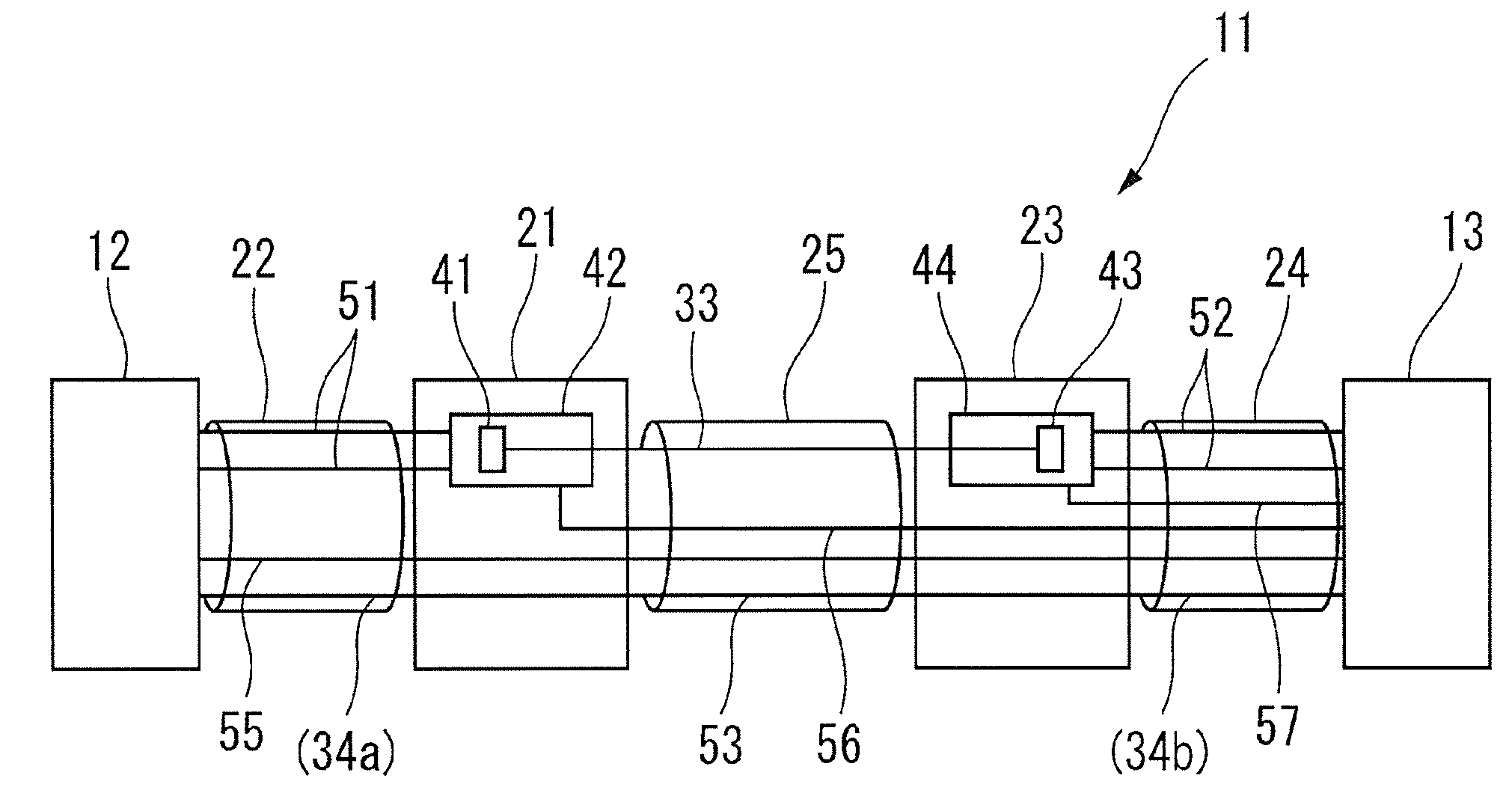
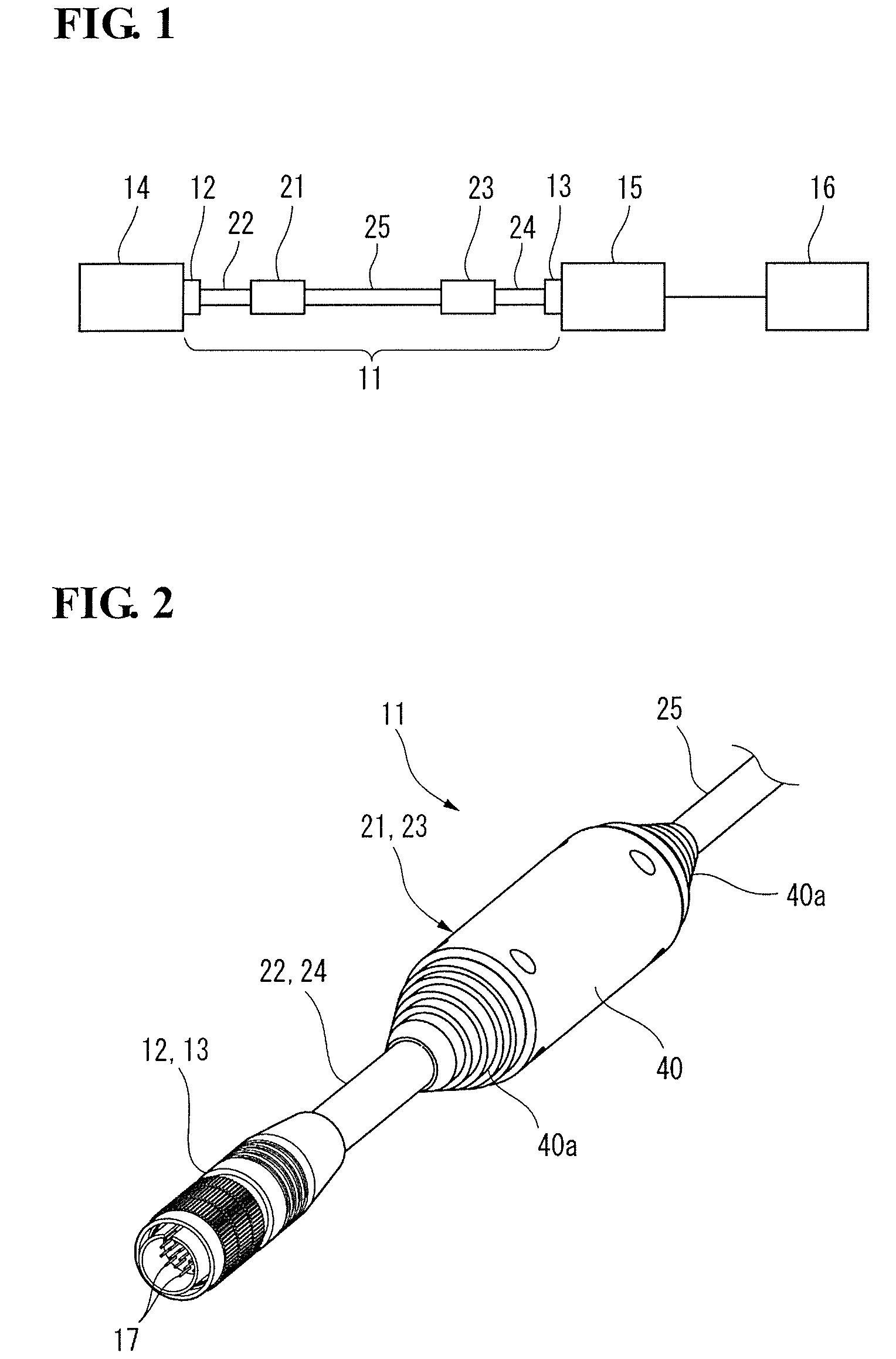
[0027]FIG. 1 is a conceptual diagram depicting an opto-electro hybrid harness 11 in the state which occurs during service according to an embodiment of the present invention. The opto-electro hybrid harness 11 has a first connector 12 at one end thereof, and has a second connector 13 at the other end. In this embodiment, the first connector 12 is connected to the receptacle of a video camera 14 and the second connector 13 is connected to the receptacle of a controller unit 15. The opto-electro hybrid harness 11 is provided with a first relay segment 21 situated away from the fi...


PUM

PropertyMeasurementUnit
electric poweraaaaaaaaaa
electricalaaaaaaaaaa
electrical continuityaaaaaaaaaa

Abstract

The An opto-electro hybrid harness includes, at locations away from first and second connectors, a first relay segment having an EO conversion device, and a second relay segment having an OE conversion device. First and second electric cables lie between the first connector and the first relay segment and between the second connector and the second relay segment. An opto-electric hybrid cable segment lies between the first and second relay segments. An optical fiber is connected at one end to the E0 conversion device and at the other end to the OE conversion device. A first electronic wire of the first electric cable is connected at one end to the first connector and at the other end to the E0 conversion device. A second electronic wire of the second electric cable is connected at one end to the OE conversion device and at the other end to the second connector.

Description

TECHNICAL FIELD[0001]The present invention relates to an opto-electro hybrid harness having an electronic wire and an optical fiber, and to a method for the manufacture thereof.BACKGROUND ART[0002]In the field of electronic devices such as medical instruments, handheld devices, compact video cameras, personal computers, personal digital assistants (PDAs), and the like, there is a need for faster communication commensurate with more advanced functionality. Communication via optical fiber is a preferred way of meeting this need. Also, in medical applications, cameras themselves have become more compact in size, giving rise to a need for more compact connectors for connection to these devices.[0003]Japanese Laid-Open Patent Application 2009-238728, discloses in FIG. 30 thereof a connector for use with an opto-electro hybrid cable that combines a small-diameter coaxial cable and an optical fiber, and in which the connector has an OE conversion module that is connected to the optical fib...

Claims


Application Information

Patent Timeline
Patent Type & Authority Patents(United States)
IPC IPC(8): G02B6/44
CPCG02B6/4416Y10T29/49117
Inventor ISHIMOTO, TAKEKICHIGUSA, YOSHIKI
Owner SUMITOMO ELECTRIC IND LTD
Learn More