Phase-locked loop
a phase-locked loop and loop technology, applied in the direction of electrical equipment, pulse automatic control, etc., can solve the problems of excessive surge energy, impose interference on oscillation signals, and prolong the locking speed of the pll b, so as to reduce the time needed for locking the pll, the effect of preventing damping
- Summary
- Abstract
- Description
- Claims
- Application Information
AI Technical Summary
Benefits of technology
Problems solved by technology
Method used
Image
Examples
first embodiment
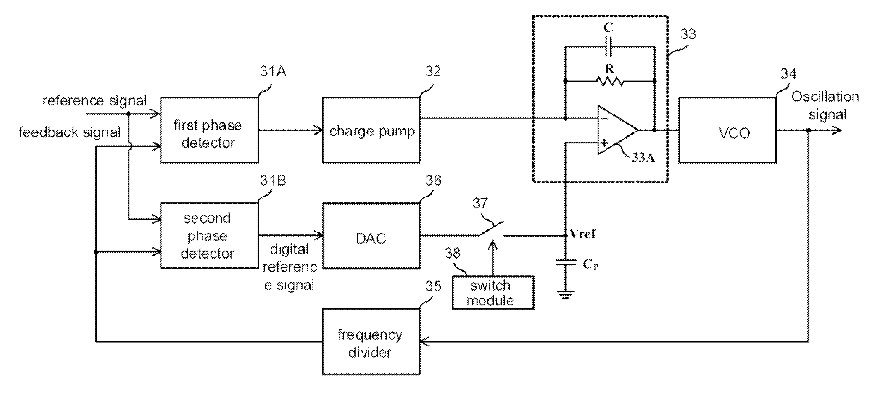
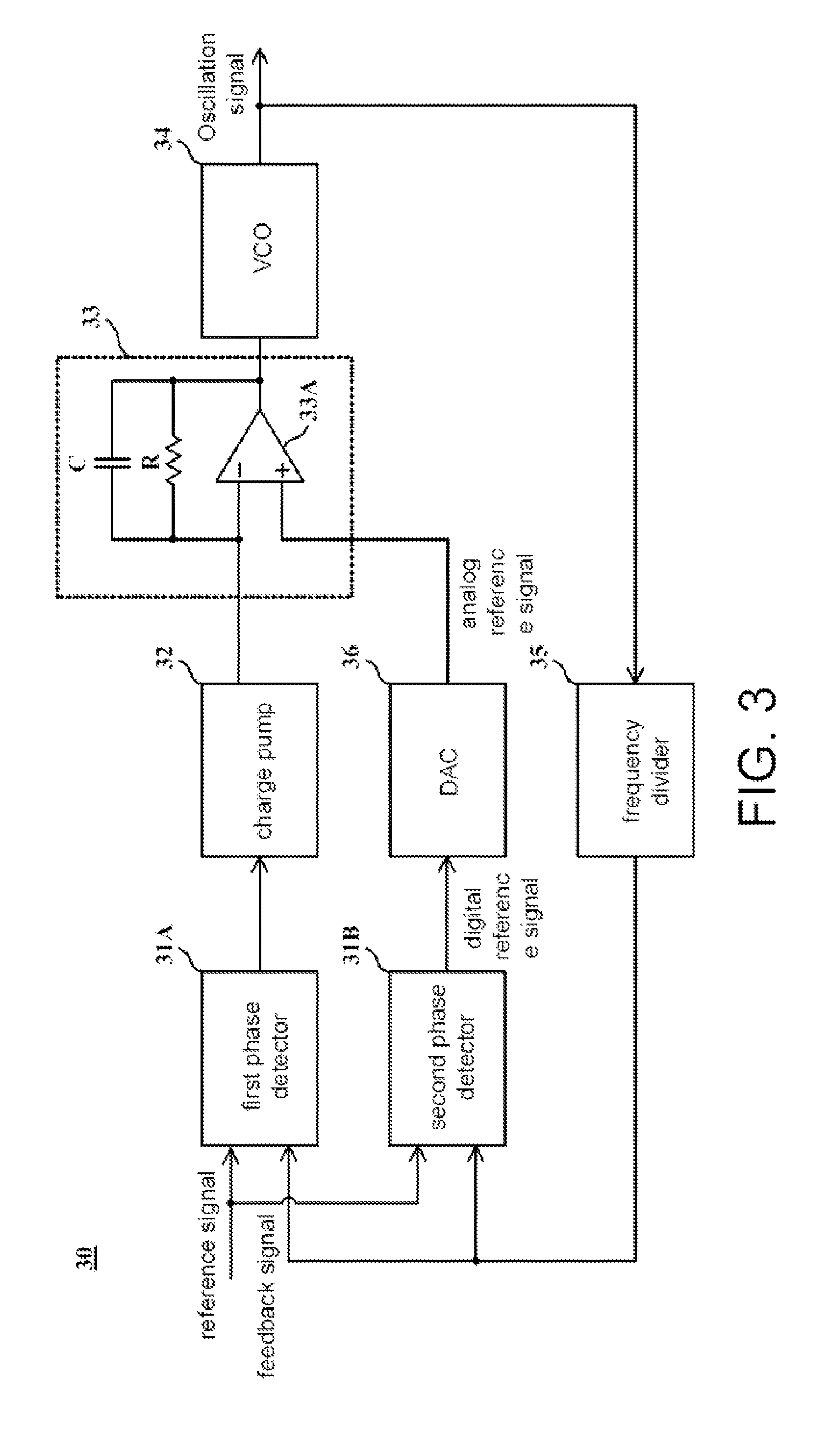
[0019]FIG. 3 shows a schematic diagram of a PLL according to the present invention. A PLL 30 comprises two phase detectors 31A and 31B, a charge pump 32, an active filter 33 consisted of a resistor R, a capacitor C and an operational amplifier 33A, a VCO 34, a frequency divider 35, and a DAC 36.
[0020]As shown in FIG. 3, the active filter 33 comprises a first input connected to the charge pump 32, a second input connected to the DAC 36, and an output for providing a control signal. The capacitor C and the resistor R are connected in parallel between the first input and the output. The VCO 34 generates an oscillation signal according to the control signal. The frequency divider 35 frequency divides the oscillation signal to generate a feedback signal. In the other words, the feedback signal associating with the oscillation signal. According to a reference signal inputted to the PLL 30 and the feedback signal, the first phase detector 31A generates a phase difference signal. The charge...
third embodiment
[0027]A PLL having a calibration function is disclosed according to the present invention. With reference to FIG. 6A, apart from the elements shown in FIG. 3, the PLL according to this embodiment further comprises a voltage detector 39, a control module 40 and a calibration module 41. In this embodiment, the charge pump 32 is designed as being capable of selectively providing a predetermined current Inorm or a test current Itest, and the frequency divider 35 is designed as being capable of selectively providing a predetermined frequency dividing amount Nnorm or a predetermined test frequency dividing amount Ntest. For example, the predetermined current Inorm and the predetermined frequency dividing amount Nnorm are a current amount and a frequency dividing amount provided to the PLL during normal operations.
[0028]When the predetermined current amount Inorm and the predetermined frequency dividing amount Nnorm are provided, a loop gain Gloop of the PLL is represented as:
[0029]Gloop=I...
fifth embodiment
[0047]A calibration method for a PLL is provided according to the present invention. The PLL comprises a charge pump and a frequency divider. The calibration method comprises steps shown in FIG. 7. In Step S71, a predetermined current amount Inorm is provided at the charge pump, and a predetermined frequency dividing a Nnorm is provided at the frequency divider. In Step S72, when the PLL is locked, a voltage associated with an output frequency of the PLL is measured to generate a first reference voltage V1. In Step S73, a test current amount Itest is provided at the charge pump, and the predetermined frequency dividing amount Nnorm is provided at the frequency divider. In Step S74, when the PLL is locked, the voltage is again measured to generate a second reference voltage V2.
[0048]In Step S75, the predetermined current amount Inorm provided at the charge pump, and a test frequency dividing amount Ntest is provided at the frequency divider, wherein the test frequency dividing amount...
PUM
 Abstract
Description
Claims
Application Information
 - R&D
- Intellectual Property
- Life Sciences
- Materials
- Tech Scout
- Unparalleled Data Quality
- Higher Quality Content
- 60% Fewer Hallucinations
Browse by: Latest US Patents, China's latest patents, Technical Efficacy Thesaurus, Application Domain, Technology Topic, Popular Technical Reports.
© 2025 PatSnap. All rights reserved.Legal|Privacy policy|Modern Slavery Act Transparency Statement|Sitemap|About US| Contact US: help@patsnap.com


